
User`s manual


Chapter 2: Installation
2-19
JPL1
J_VMEM
JL1
LE2
LE1
JBT1
LAN1
LAN2
BIOS
SIMSO IPMI
LAN
CTRL
Battery
LE3
J4
VGA
CTRL
SMB
JPL2
SGPIO
CPLD
Intel
5400
North Bridge
CPU 2
FP CTRL
JWD
CPU 1
FAN1/2
20-Pin PWR
PWSMB
CTRL
InfiniBand
DIMM2B
DIMM2A
DIMM1B
DIMM1A
20-Pin PWR
4-Pin Aux. PWR
S I/O
JPG1
JWOL
Intel ESB2
South Bridge
FAN3/4
JSPK
COM1
SATA2
DIMM4B
FPUSB2/3
BANK4
USB0/1
DIMM4A
DIMM3B
DIMM3A
BANK3
BANK2BANK1
VGA
SATA3
SATA0
SATA1
PCI-Express x16
FAN5/6
FAN7/8
Infini- Band
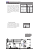
X7DWT-INF
A. PWR SMB
B. Wake-on-LAN
A
B
Power SMB (I
2
C) Connector
Power SMB (I
2
C) Connector (J17)
monitors the status of the power
supply, fan speed, and system tem-
perature. See the table on the right
for pin defi nitions.
PWR SMB
Pin Defi nitions
Pin# Defi nition
1Clock
2 Data
3 PWR Fail
4 Ground
5+3.3V
Wake-On-LAN
The Wake-On-LAN header is located
at JWOL on the motherboard. See
the table on the right for pin defi ni-
tions. (You must also have a LAN
card with a Wake-On-LAN connector
and cable to use this feature.)
Wake-On-LAN
Pin Defi nitions
Pin# Defi nition
1 +5V Standby
2 Ground
3 Wake-up