
User`s manual


Chapter 2: Installation
2-15
JPL1
J_VMEM
JL1
LE2
LE1
JBT1
LAN1
LAN2
BIOS
SIMSO IPMI
LAN
CTRL
Battery
LE3
J4
VGA
CTRL
SMB
JPL2
SGPIO
CPLD
Intel
5400
North Bridge
CPU 2
FP CTRL
JWD
CPU 1
FAN1/2
20-Pin PWR
PWSMB
CTRL
InfiniBand
DIMM2B
DIMM2A
DIMM1B
DIMM1A
20-Pin PWR
4-Pin Aux. PWR
S I/O
JPG1
JWOL
Intel ESB2
South Bridge
FAN3/4
JSPK
COM1
SATA2
DIMM4B
FPUSB2/3
BANK4
USB0/1
DIMM4A
DIMM3B
DIMM3A
BANK3
BANK2BANK1
VGA
SATA3
SATA0
SATA1
PCI-Express x16
FAN5/6
FAN7/8
Infini- Band
X7DWT-INF
Required Connection
D
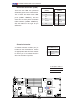
4-pin Auxiliary Power
Connector
In addition to two 20-pin power con-
nectors, a 4-pin 12V PWR supply is
located at JP10 on the motherboard.
This power connector is used to
provide power supply to hard drive
disks. Refer to the layout below for
the location.
Note1: The 4-pin Auxiliary Power
Connector is used for power supply
output to the HDDs only.
Note 2: The black square (dot) on the
power connector indicates the loca-
tion of Pin 1. (See the pictures below
for the power cable connections.)
A. 4-pin Aux. PWR
B. One Male (Receptacle)
PWR Connector
C.& D. Two Female PWR
Connectors
A
A
B
B
C
4-Pin Power
Pin Defi nitions
Pin # Defi nition
1 +12V
2 Ground
3 Ground
5 +5V