SUPER X7DVL-L USER’S MANUAL Revision 1.
The information in this User’s Manual has been carefully reviewed and is believed to be accurate. The vendor assumes no responsibility for any inaccuracies that may be contained in this document, makes no commitment to update or to keep current the information in this manual, or to notify any person or organization of the updates. Please Note: For the most up-to-date version of this manual, please see our web site at www.supermicro.com. Super Micro Computer, Inc.
Preface Preface About This Manual This manual is written for system integrators, PC technicians and knowledgeable PC users. It provides information for the installation and use of the X7DVL-L motherboard. The X7DVL-L supports dual Intel QuadCore and Dual-Core Xeon 5300/5100/5000 Series processors with a front side bus speed of 1.333 GHz/1.066 GHz/667 MHz (Note).
X7DVL-L User's Manual Table of Contents Preface About This Manual ...................................................................................................... iii Manual Organization ................................................................................................... iii Conventions Used in the Manual .................................................................................. iii Chapter 1: Introduction 1-1 Overview .........................................................
Table of Contents Power Button .......................................................................................... 2-13 2-5 Connecting Cables ......................................................................................... 2-14 ATX Power Connector .......................................................................... 2-14 Processor Power Connector ................................................................. 2-14 Universal Serial Bus (USB) ............................................
X7DVL-L User's Manual Memory Errors........................................................................................... 3-2 3-2 Technical Support Procedures ........................................................................ 3-2 3-3 Frequently Asked Questions ........................................................................... 3-3 3-4 Returning Merchandise for Service ................................................................. 3-4 Chapter 4: BIOS 4-1 Introduction ............
Chapter 1: Introduction Chapter 1 Introduction 1-1 Overview Checklist Congratulations on purchasing your computer motherboard from an acknowledged leader in the industry. Supermicro boards are designed with the utmost attention to detail to provide you with the highest standards in quality and performance. Check that the following items have all been included with your motherboard. If anything listed here is damaged or missing, contact your retailer. All items are included in the retail box.
X7DVL-L User's Manual Contacting Supermicro Headquarters Address: Super Micro Computer, Inc. 980 Rock Ave. Tel: San Jose, CA 95131 U.S.A. +1 (408) 503-8000 Fax: +1 (408) 503-8008 Email: marketing@supermicro.com (General Information) Web Site: support@supermicro.com (Technical Support) www.supermicro.com Europe Address: Tel: Fax: Email: Super Micro Computer B.V. Het Sterrenbeeld 28, 5215 ML 's-Hertogenbosch, The Netherlands +31 (0) 73-6400390 +31 (0) 73-6416525 sales@supermicro.
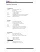
Chapter 1: Introduction X7DVL-L Image Note: The drawings and graphics shown in this manual were based on the latest PCB Revision available at the time of publishing of the manual. The motherboard you’ve received may or may not look exactly the same as the graphics shown in the manual.
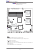
X7DVL-L User's Manual X7DVL-L Motherboard Layout JPW1 JKM1 KB/MS JPW3 (not drawn to scale) Fan 1 24-Pin PWR 8-Pin PWR CPU 1 DIMM2B J7B3 JCOM1 J8B1 J20 USB0/1 LE2 J7B2 DIMM2A DIMM1B J7B1 COM1 VGA DIMM1A J15 GLAN1 JPF JP2 PWR Force North Bridge JLAN1 LAN CTRL GLAN2 CPU 2 JLAN2 Battery BIOS J10 VGA CTRL Fan 2 LE6 South Bridge Slot 6 PCI-Ex8 LE5 J19 JWD JPG1 JI2C1 JI2C2 JPL1 JPL2 LE4 Fan 3 IDE#1 D31 JBT1 VGA Memory FAN5 S I/O J6 Fan 4 Floppy J22 JUSB1 Buzzer C
Chapter 1: Introduction Quick Reference (X7DVL-L) Jumper Description Default Setting JBT1 JI2C1/JI2C2 CMOS Clear (See Pg. 2-23) SMB to PCI Slot#1/Slot#2 Speed Pins 2-3 (Disabled) JPG1 JPL1/ JPL2 VGA Enable GLAN1/GLAN2 Enable Pins 1-2 (Enabled) Pins 1-2 (Enabled) JWD Watch Dog Pins 1-2 (Reset) Connector Description ATX PWR (JPW1) CPU PWR (JPW3) Primary 24-Pin ATX PWR Connector +12V 8-pin PWR Chassis Intru.
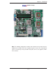
X7DVL-L User's Manual Motherboard Features CPU • Dual Intel® 64-bit LGA 771 Quad-Core/Dual-Core Xeon 5300/5100/5000 Series processors at a front side bus speed of 1.333 GHz/1.066 GHz/667 MHz (Note: CPUs with 90W or less are recommended.) Memory • Four 240-pin DIMM sockets with support up to 16 GB ECC FBD (Fully Buffered) DDR2 667/533 Memory (See Section 2-3 in Chapter 2 for DIMM Slot Population.
Chapter 1: Introduction ACPI Features • Slow blinking LED for suspend state indicator • Main switch override mechanism • ACPI Power Management • Power-on mode for power recovery Onboard I/O • Intel ESB2 supports four SATA ports (with RAID0, RAID1, RAID10 and RAID5 supported in the Window OS environment) • The 82563EB supports two Giga-bit LAN ports • One EIDE Ultra DMA/100 bus master interface • One floppy port interface • Two COM ports(1 header, 1 port) • Up to four USB 2.
X7DVL-L User's Manual PROCESSOR#2 VRM ISL6312 PROCESSOR#1 FBD CHNL0 PORT #4,5 MCH #1B #1A #2B #2A FBD DIMM 1067/1333 MT/S 1067/1333 MT/S FBD DIMM VRM ISL6312 FBD CHNL1 PORT #6,7 J10 #6 PORT #1,2 ATA 100 PORTPORT #3 #4 PORT #0 #0 IDE CONN #3 #2 #1 3.0 Gb/S ESB2 SATA PCI-EXP x8 PCIEx4 PCIEx8 PCI-EXP_x8_SLOT PORT PORT #0 #2,3 CONN VGA XGI Z7 3.0 Gb/S #3 #2 #1 #0 USB 2.
Chapter 1: Introduction 1-2 Chipset Overview Built upon the functionality and the capability of the 5000V (Blackford-VS) chipset, the X7DVL-L motherboard provides the performance and feature set required for dual processor-based servers with configuration options optimized for communications, presentation, storage, computation or database applications.
X7DVL-L User's Manual 1-3 Special Features Recovery from AC Power Loss BIOS provides a setting for you to determine how the system will respond when AC power is lost and then restored to the system. You can choose for the system to remain powered off (in which case you must hit the power switch to turn it back on) or for it to automatically return to a power- on state. See the Power Lost Control setting in the Advanced Setup section to change this setting. The default setting is Last State.
Chapter 1: Introduction System Resource Alert This feature is available when used with Supero Doctor III in the Windows OS environment or used with Supero Doctor II in Linux. Supero Doctor is used to notify the user of certain system events. For example, if the system is running low on virtual memory and there is insufficient hard drive space for saving the data, you can be alerted of the potential problem.
X7DVL-L User's Manual External Modem Ring-On Wake-up events can be triggered by a device such as the external modem ringing when the system is in the Standby or Off state. Note that external modem ring-on can only be used with an ATX 2.01 (or above) compliant power supply. Wake-On-LAN Wake-On-LAN is defined as the ability of a management application to remotely power up a computer that is powered off.
Chapter 1: Introduction for interfacing with floppy disk drives. The Super I/O supports 360 K, 720 K, 1.2 M, 1.44 M or 2.88 M disk drives and data transfer rates of 250 Kb/s, 500 Kb/s or 1 Mb/s.It also provides two high-speed, 16550 compatible serial communication ports (UARTs). Each UART includes a 16-byte send/receive FIFO, a programmable baud rate generator, complete modem control capability and a processor interrupt system. Both UARTs provide legacy speed with baud rate of up to 115.
X7DVL-L User's Manual Notes 1-14
Chapter 2: Installation Chapter 2 Installation 2-1 Static-Sensitive Devices Electric-Static-Discharge (ESD) can damage electronic components. To prevent damage to your system board, it is important to handle it very carefully. The following measures are generally sufficient to protect your equipment from ESD. Precautions • Use a grounded wrist strap designed to prevent static discharge. • Touch a grounded metal object before removing the board from the antistatic bag.
X7DVL-L User's Manual 2-2 Processor and Heatsink Installation ! When handling the processor package, avoid placing direct pressure on the label area of the fan. *Notes: 1. Always connect the power cord last and remove it before adding, removing or changing any components. Make sure to install the processor into the CPU socket before you install the CPU heatsink. 2. Intel's boxed Xeon CPU package contains the CPU fan and heatsink assembly.
Chapter 2: Installation 2. Locate the front side of the chassis. 3. Locate the four backplate mounting holes on the chassis. 4. Align the backplate with the chassis. Make sure that the arrow on the backplate is pointing at the front side of the chassis. The Front Side of Chassis 5. Once the backplate is correctly oriented, align the four heatsink mounting holes on the backplate against their respective Mounting mounting holes on the chassis.
X7DVL-L User's Manual 3. Use your thumb and index finger to hold the CPU at the North Center Edge and the Load Plate South Center Edge of the CPU. (w/PnP Cap attached) 4. Align CPU Pin1 (the CPU corner marked with a triangle) against the socket corner that is marked with a triangle cutout. North Center Edge South Center 5. Align the CPU key that is the semi-circle cutout below a gold dot against the socket key, the notch on the same side of the triangle cutout on the socket. 6.
Chapter 2: Installation Installation and Removal of the Heatsink CEK Passive Heatsink CEK Heatsink Installation 1. Do not apply any thermal grease to the heatsink or the CPU die; the required amount Screw#1 has already been applied. Screw#2 2. Place the heatsink on top of the CPU so that the four mounting holes are aligned with those on the retention mechanism. 3.
X7DVL-L User's Manual 2-3 Installing DIMMs Note: Check the Supermicro web site for recommended memory modules. CAUTION Exercise extreme care when installing or removing DIMM modules to prevent any possible damage. Also note that the memory is interleaved to improve performance (see step 1). DIMM Installation 1. Insert the desired number of DIMMs into the memory slots, starting with DIMM #1A. (*See the Memory Installation Table Below.) 2. Insert each DIMM module vertically into its slot.
Chapter 2: Installation Possible System Memory Allocation & Availability System Device Size Physical Memory Remaining (-Available) (4 GB Total System Memory) Firmware Hub flash memory (System BIOS) 1 MB 3.99 Local APIC 4 KB 3.99 Area Reserved for the chipset 2 MB 3.99 I/O APIC (4 Kbytes) 4 KB 3.99 PCI Enumeration Area 1 256 MB 3.76 PCI Express (256 MB) 256 MB 3.51 PCI Enumeration Area 2 (if needed) -Aligned on 256-MB boundary- 512 MB 3.01 VGA Memory 16 MB 2.85 TSEG 1 MB 2.
X7DVL-L User's Manual 2-4 Control Panel Connectors/IO Ports The I/O ports are color coded in conformance with the PC 99 specification. See Figure 2-3 below for the colors and locations of the various I/O ports. A. Back Panel Connectors/IO Ports 2 4 1 3 5 6 7 Back Panel I/O Port Locations and Definitions Back Panel Connectors 1. Keyboard (Purple) 2. PS/2 Mouse (Green) 3. Back Panel USB Port 0 4. Back Panel USB Port 1 5. COM Port 1 (Turquoise) 6. VGA Port (Blue) 7. Gigabit LAN 1 8.
Chapter 2: Installation B. Front Control Panel JF1 contains header pins for various buttons and indicators that are normally located on a control panel at the front of the chassis. These connectors are designed specifically for use with Supermicro server chassis. See Figure 2-4 for the descriptions of the various control panel buttons and LED indicators. Refer to the following section for descriptions and pin definitions.
X7DVL-L User's Manual C. Front Control Panel Pin Definitions NMI Button NMI Button Pin Definitions (JF1) The non-maskable interrupt button Pin# Definition header is located on pins 19 and 20 19 Control 20 Ground of JF1. Refer to the table on the right for pin definitions. Power LED Power LED Pin Definitions (JF1) The Power LED connection is located on pins 15 and 16 of JF1. Refer to the table on the right for pin definitions. Pin# Definition 15 +5V 16 Ground A. NMI B.
Chapter 2: Installation HDD LED HDD LED Pin Definitions (JF1) The HDD LED connection is located on pins 13 and 14 of JF1. Attach a hard drive LED cable here to display disk activities (for any hard drives on Pin# Definition 13 +5V 14 HD Active the system, including Serial ATA and IDE). See the table on the right for pin definitions.
X7DVL-L User's Manual Overheat/Fan Fail LED (OH) OH/Fan Fail LED Pin Definitions (JF1) Connect an LED to the OH/Fan Fail connection on pins 7 and 8 of JF1 Pin# Definition 7 Vcc to provide advanced warnings of chassis overheating or fan failure. 8 Ground Refer to the table on the right for pin OH/Fan Fail Indicator Status definitions.
Chapter 2: Installation Reset Button The Reset Button connection is located Reset Button Pin Definitions (JF1) on pins 3 and 4 of JF1. Attach it to the hardware reset switch on the computer case. Refer to the table on the right for Pin# Definition 3 Reset pin definitions. 4 Ground Power Button Power Button Pin Definitions (JF1) The Power Button connection is located on pins 1 and 2 of JF1. Momentarily contacting both pins will power on/off the system.
X7DVL-L User's Manual 2-5 Connecting Cables ATX Power 20-pin Connector Pin Definitions Pin# Definition 13 +3.3V 1 +3.3V There are a 24 -pin main power 14 -12V 2 +3.3V supply connector(JPW1) and an 15 COM 3 COM 8-pin CPU PWR connector (JPW3) on the motherboard. These power 16 PS_ON 4 +5V 17 COM 5 COM connectors meet the SSI EPS 12V 18 COM 6 +5V specification.
Chapter 2: Installation Back Panel USB (USB0/1) Universal Serial Bus (USB) There are four USB 2.0 (Universal Pin# Definitions Serial Bus) ports/headers on the 1 +5V motherboard. USB Ports 0/1 (J20) are located on the I/O Back Panel, 2 PO- 3 PO+ and USB Headers 2/3 (JUSB1) can 4 Ground be accessed from the Front Panel. 5 N/A See the tables on the right for pin Front Panel USB Pin Definitions definitions.
X7DVL-L User's Manual Fan Headers Fan Header Pin Definitions (Fan1-6) The X7DVL-L has three chassis/system fan headers (Fan3 to Fan5) and two CPU Fans (Fans 1/2). (*Note: all these fans are 4-pin fans. However, Pins 1-3 of the fan headers are backward compatible with the traditional 3-pin fans.) See the table on the right for pin definitions.
Chapter 2: Installation ATX PS/2 Keyboard and PS/2 Mouse Ports PS/2 Keyboard and Mouse Port Pin Definitions The ATX PS/2 keyboard and the PS/2 Pin# Definition mouse are located at JKM1. See the 1 Data table on the right for pin definitions. (The mouse port is above the key- 2 NC 3 Ground board port. See the table on the right 4 VCC for pin definitions.
X7DVL-L User's Manual Wake-On-Ring Wake-On-Ring Pin Definitions (JWOR1) The Wake-On-Ring header is designated JWOR1. This function allows Pin# Definition your computer to be awakened by an incoming call to the modem when the 1 Ground 2 Wake-up system is in suspend state. See the table on the right for pin definitions. You must have a Wake-On-Ring card and cable to use this feature. Wake-On-LAN Wake-On-LAN Pin Definitions (JWOL1) The Wake-On-LAN header is located at JWOL1 on the motherboard.
Chapter 2: Installation GLAN 1/2 (Giga-bit Ethernet Ports) Two G-bit Ethernet ports: GLAN1 GLAN1 GLAN2 (JLAN1) and GLAN2 (JLAN2) are located on the I/O backplane. These ports accept RJ45 type cables. Power LED/Speaker Speaker Connector On the JD1 header, pins 1-3 are for a power LED and pins 4-7 are for the speaker. Close pins 4-7 with a jumper to use an external speaker. If you wish to use the onboard speaker, please close pins 6-7. See the table on the right for speaker pin definitions.
X7DVL-L User's Manual T-SGPIO Header T-SGPIO Pin Definitions The T-SGPIO (Serial General Purpose Pin# Definition Pin Definition on the motherboard. This header is used to "talk to" a system-monitoring 1 *NC 2 *NC 3 Ground 4 DATA Out chip on the backplane. See the table 5 Load 6 Ground on the right for pin definitions. Refer to 7 Clock 8 *NC Input/Output) header is located at J26 the board layout below for the location *Note: NC= No Connections of the header.
Chapter 2: Installation 2-6 Jumper Settings Explanation of Jumpers Connector Pins To modify the operation of the motherboard, 3 2 1 3 2 1 jumpers can be used to choose between optional settings. Jumpers create shorts between two pins to change the function Jumper Cap of the connector. Pin 1 is identified with a square solder pad on the printed circuit board. See the motherboard layout pages Setting for jumper locations.
X7DVL-L User's Manual CMOS Clear JBT1 is used to clear CMOS. Instead of pins, this "jumper" consists of contact pads to prevent the accidental clearing of CMOS. To clear CMOS, use a metal object such as a small screwdriver to touch both pads at the same time to short the connection. Always remove the AC power cord from the system before clearing CMOS. Note: For an ATX power supply, you must completely shut down the system, remove the AC power cord and then short JBT1 to clear CMOS.
Chapter 2: Installation VGA Enable/Disable VGA Enable/Disable Jumper Settings JPG1 allows you to enable or disable the VGA port. The default position is on pins 1 and 2 to enable VGA. See the table on the right for jumper settings. Both Jumpers Definition Pins 1-2 Enabled (*Default) Pins 2-3 Disabled I2C Bus to PCI Slots I2C to PCI-Slots Jumper Settings Jumpers JI2C1/JI2C2 allow you to connect the System Management Bus (I2C) to PCI slots.
X7DVL-L User's Manual 2-7 Onboard Indicators Link Activity LED LED (Rear View: When viewing from the rear side of the chassis.) GLAN LEDs There are two GLAN ports on the moth- GLAN Activity Indicator erboard. Each Gigabit Ethernet LAN port has two LEDs. The yellow LED indicates activity, while the other LED may be Color Status Definition Yellow Flashing Active green, amber or off to indicate the speed GLAN Link Indicator of the connection. See the tables at right for more information.
Chapter 2: Installation POST Code LED Indicators (LE4, LE5) POST Code LED Indicators There are two POST Code LED Indica- LE4 tors (LE4, LE5) located on the moth- Green: On Yellow: Off erboard.
X7DVL-L User's Manual CPU VRM Overheat LED Indicators (LE2/LE6) CPU VRM Overheat LEDs (LE2, LE6) There are two CPU VRM Overheat LED LED Color Definition Indicators (LE2 and LE6) are on the moth- Off erboard. LE2 is for CPU1VRM and LE6 is for CPU2 VRM. If the temperature of a CPU CPU VRM Temperature: Normal Yellow 0 CPU VRM over 90 C, CPU slows down VRM is normal, its CPU VRM Overheat LED is off.
Chapter 2: Installation 2-8 Floppy Drive and Hard Disk Drive Connections Note the following when connecting the floppy and hard disk drive cables: • The floppy disk drive cable has seven twisted wires. • A red mark on a wire typically designates the location of pin 1. Floppy Drive Connector Pin Definitions Floppy Connector Pin# Definition J22. See the table below for pin 1 Ground 2 FDHDIN definitions.
X7DVL-L User's Manual IDE Connector IDE Drive Connectors Pin Definitions An IDE Connector is located at JIDE1 Pin# Definition on the motherboard. See the table on 1 Reset IDE 2 Ground the right for pin definitions.
Chapter 3: Troubleshooting Chapter 3 Troubleshooting 3-1 Troubleshooting Procedures Use the following procedures to troubleshoot your system. If you have followed all of the procedures below and still need assistance, refer to the ‘Technical Support Procedures’ and/or ‘Returning Merchandise for Service’ section(s) in this chapter. Note: Always disconnect the power cord before adding, changing or installing any hardware components. Before Power On 1.
X7DVL-L User's Manual Losing the System’s Setup Configuration 1. Make sure that you are using a high quality power supply. A poor quality power supply may cause the system to lose the CMOS setup information. Refer to Section 1-6 for details on recommended power supplies. 2. The battery on your motherboard may be old. Check to make sure that it still supplies ~3VDC. If it does not, replace it with a new one. 3. If the above steps do not fix the Setup Configuration problem, contact your vendor for repairs.
Chapter 3: Troubleshooting com/support/bios/) 3. If you still cannot resolve the problem, include the following information when contacting Super Micro for technical support: • Motherboard model and PCB revision number • BIOS release date/version (this can be seen on the initial display when your system first boots up) •System configuration An example of a Technical Support form is on our web site at (http://www. supermicro.com/support/contact.cfm). 4.
X7DVL-L User's Manual (Warning: Do not shut down or reset the system while updating BIOS to prevent possible system boot failure!) Question: What's on the CD that came with my motherboard? Answer: The supplied compact disc has quite a few drivers and programs that will greatly enhance your system. We recommend that you review the CD and install the applications you need. Applications on the CD include chipset drivers, security and audio drivers.
Chapter 4: BIOS Chapter 4 BIOS 4-1 Introduction This chapter describes the Phoenix BIOS™ Setup utility for the X7DVL-L. The Phoenix ROM BIOS is stored in a flash chip and can be easily upgraded using a floppy disk-based program. Note: Due to periodic changes to the BIOS, some settings may have been added or deleted and might not yet be recorded in this manual. Please refer to the Manual Download area of the Super Micro web site
X7DVL-L User's Manual 4-2 Running Setup *Default settings are in bold text unless otherwise noted. The BIOS setup options described in this section are selected by choosing the appropriate text from the main BIOS Setup screen. All displayed text is described in this section, although the screen display is often all you need to understand how to set the options (see the next page). When you first power on the computer, the Phoenix BIOS™ is immediately activated.
Chapter 4: BIOS Main BIOS Setup Menu Main Setup Features System Time To set the system date and time, key in the correct information in the appropriate fields. Then press the key to save the data. System Date Using the arrow keys, highlight the month, day and year fields, and enter the correct data. Press the key to save the data. BIOS Version This field displays the current BIOS version. BIOS Date This field displays the date when this version of BIOS was built.
X7DVL-L User's Manual IDE Channel 0 Master/Slave, IDE Secondary Master/Slave, SATA Port2 and SATA Port3 These settings allow the user to set the parameters of IDE Channel 0 Master/ Slave, IDE Channel 1 Master/Slave, IDE Channel 2 Master, IDE Channel 3 Master slots. Hit to activate the following sub-menu screen for detailed options of these items. Set the correct configurations accordingly.
Chapter 4: BIOS CHS Format The following items will be displayed by the BIOS: TYPE: This item displays the type of IDE or SATA Device. Cylinders: This item indicates the status of Cylinders. Headers: This item indicates the number of headers. Sectors: This item displays the number of sectors. Maximum Capacity: This item displays the maximum storage capacity of the system.
X7DVL-L User's Manual Parallel ATA This setting allows the user to enable or disable the function of the Parallel ATA. The options are Disabled and Enabled. Serial ATA This setting allows the user to enable or disable the function of the Serial ATA. The options are Disabled and Enabled. Native Mode Operation Select the native mode for ATA. The options are: Parallel ATA, Serial ATA, Both, and Auto.
Chapter 4: BIOS 4-4 Advanced Setup Choose Advanced from the Phoenix BIOS Setup Utility main menu with the arrow keys. You should see the following display. The items with a triangle beside them have sub menus that can be accessed by highlighting the item and pressing . Boot Features Access the submenu to make changes to the following settings. QuickBoot Mode If enabled, this feature will speed up the POST (Power On Self Test) routine by skipping certain tests after the computer is turned on.
X7DVL-L User's Manual Power Button Behavior If set to Instant-Off, the system will power off immediately as soon as the user hits the power button. If set to 4-sec., the system will power off when the user presses the power button for 4 seconds or longer. The options are instant-off and 4-sec override. Resume On Modem Ring Select On to “wake your system up” when an incoming call is received by your modem. The options are On and Off.
Chapter 4: BIOS area of Block 0-512K. Select Write Back to allow the CPU to write data back directly from the buffer without writing data to the System Memory for fast CPU data processing and operation. The options are Uncached, Write Through, Write Protect, and Write Back.
X7DVL-L User's Manual Emulated IRQ Solution All PCI-E devices are required to support MSI (Message Signaled Interrupt); however, some legacy operating systems do not support MSI. When this feature is set to Enabled, a PCI-E device will generate a device-specific address and interrupt vector number stored in the device's MSI and data registers which will be initialized by BIOS before a "non-MSI-aware" OS boots up in order to enhance system performance. The options are Enabled and Disabled.
Chapter 4: BIOS Option ROM Scan When enabled, this setting will initialize the device expansion ROM. The options are Enabled and Disabled. Enable Master This setting allows you to enable the selected device as the PCI bus master. The options are Enabled and Disabled. Latency Timer This setting allows you to set the clock rate for Bus Master. A high-priority, highthroughout device may benefit from a greater clock rate. The options are Default, 0020h, 0040h, 0060h, 0080h, 00A0h, 00C0h, and 00E0h.
X7DVL-L User's Manual Branch 0 Rank Sparing Select enable to enable the sparing feature for Branch 0 Rank. The options are Enabled and Disabled. Enhanced x8 Detection Select Enabled to enable Enhanced x8 DRAM UC Error Detection. The options are Disabled and Enabled. High Bandwidth FSB Select Enabled to enable high bandwidth Front Side Bus (FSB). The options are Enabled and Disabled.
Chapter 4: BIOS Route Port 80h Cycles to This feature allows the user to decide which bus to send debug information to. The options are Disabled, PCI and LPC. Clock Spectrum Feature If Enabled, the BIOS will monitor the level of Electromagnetic Interference caused by the components and will attempt to decrease the interference whenever needed. The options are Enabled and Disabled.
X7DVL-L User's Manual to detect and report hardware (machine) errors via a set of model-specific registers (MSRs). The options are Disabled and Enabled. Thermal Management 2 (Available when supported by the CPU.) Set to Enabled to use Thermal Management 2 (TM2) which will lower CPU voltage and frequency when the CPU temperature reaches a predefined overheat threshold.
Chapter 4: BIOS Intel Virtualization Technology (*Available when supported by the CPU.) Select Enabled to use the feature of Virtualization Technology to allow one platform to run multiple operating systems and applications in independent partitions, creating multiple "virtual" systems in one physical computer. The options are Enabled and Disabled. (Note: If there is any change to this setting, you will need to power off and restart the system for the change to take effect.
X7DVL-L User's Manual Interrupt This setting allows you to select the IRQ (interrupt request) for serial port B. The options are IRQ3 and IRQ4. Parallel Port This setting allows you to assign control of the parallel port. The options are Enabled (user defined), Disabled and Auto (BIOS-or OS- controlled). Base I/O Address Select the base I/O address for the parallel port. The options are 378, 278 and 3BC. Interrupt This setting allows you to select the IRQ (interrupt request) for the parallel port.
Chapter 4: BIOS ECC Event Logging This setting allows you to Enable or Disable ECC event logging. Mark DMI Events as Read Highlight this item and press to mark the DMI events as read. Clear All DMI Event Logs Select Yes and press to clear all DMI event logs. The options are Yes and No. Console Redirection Access the submenu to make changes to the following settings.
X7DVL-L User's Manual Hardware Monitor Logic Highlight an item and hit to see the status of each of the following items: CPU Overheat Alarm This option allows the user to select the CPU Overheat Alarm setting which determines when the CPU OH alarm will be activated to provide warning of possible CPU overheat. Refer to the next item, CPU Temperature for more information regarding PECI, DTS and other thermal features of this motherboard.
Chapter 4: BIOS The Default Alarm – the Overheat LED and system buzzer will activate if the High condition continues for some time after it is reached. The CPU fan will run at full speed to bring the CPU temperature down. If the CPU temperature still increases even with the CPU fan running at full speed, the system buzzer will activate and the Overheat LED will turn on. The Early Alarm – the Overheat LED and system buzzer will be activated exactly when the High level is reached.
X7DVL-L User's Manual Fan1-Fan6 Speeds: If the feature of Auto Fan Control is enabled, the BIOS will automatically display the status of the fans indicated in this item. Fan Speed Control Modes This feature allows the user to decide how the system controls the speeds of the onboard fans. The CPU temperature and the fan speed are correlative. When the CPU on-die temperature increases, the fan speed will also increase, and vice versa. If the option is set to 3-pin fan, the fan speed is controlled by voltage.
Chapter 4: BIOS IPMI (The option is available only when an IPMI card is installed in the system.) IPMI Specification Version: This item displays the current IPMI Version. Firmware Version: This item displays the current Firmware Version. System Event Logging Select Enabled to enable IPMI Event Logging. When this function is set to Disabled, the system will continue to log events received via system interface. The options are Enabled and Disabled.
X7DVL-L User's Manual OS Boot Watch Dog Set to Enabled to enable OS Boot Watch Dog. The options are Enabled and Disabled. Timer for Loading OS (Minutes) This feature allows the user to set the time value (in minutes) for the previous item: OS Boot Watch Dog by keying-in a desired number in the blank. The default setting is 10 (minutes.) (Please ignore this option when OS Boot Watch Dog is set to "Disabled".
Chapter 4: BIOS Realtime Sensor Data This feature display information from motherboard sensors, such as temperatures, fan speeds and voltages of various components.
X7DVL-L User's Manual IPMI LAN Configuration The following features allow the user to configure and monitor IPMI LAN settings. VLAN Tagging Select Enabled to enable Virtual LAN(s) for IPMI connections and allow the user to configure VLAN settings. The options are Enabled and Disabled. VLAN ID If VLAN Tagging above is set to Enabled, this item allows the user to change the VLAN ID. If VLAN Tagging is disabled, this item will be ignored by the firmware.
Chapter 4: BIOS 4-5 Security Choose Security from the Phoenix BIOS Setup Utility main menu with the arrow keys. You should see the following display. Security setting options are displayed by highlighting the setting using the arrow keys and pressing . All Security BIOS settings are described in this section. Supervisor Password Is: This indicates if a supervisor password has been entered for the system.
X7DVL-L User's Manual Password on Boot This setting allows you to determine if a password is required for a user to enter the system at bootup. The options are Enabled (password required) and Disabled (password not required). 4-6 Boot Choose Boot from the Phoenix BIOS Setup Utility main menu with the arrow keys. You should see the following display. See details on how to change the order and specs of boot devices in the Item Specific Help window. All Boot BIOS settings are described in this section.
Chapter 4: BIOS 4-7 Exit Choose Exit from the Phoenix BIOS Setup Utility main menu with the arrow keys. You should see the following display. All Exit BIOS settings are described in this section. Exit Saving Changes Highlight this item and hit to save any changes you made and to exit the BIOS Setup utility. Exit Discarding Changes Highlight this item and hit to exit the BIOS Setup utility without saving any changes you may have made.
X7DVL-L User's Manual Notes 4-28
Appendix A: POST Error Beep Codes Appendix A POST Error Beep Codes This section lists POST (Power On Self Test) error beep codes for the Phoenix BIOS. POST error beep codes are divided into two categories: recoverable and terminal. This section lists Beep Codes for recoverable POST errors. Recoverable POST Error Beep Codes When a recoverable type of error occurs during POST, BIOS will display a POST code that describes the problem.
X7DVL-L User's Manual Notes A-2
Appendix B: Installing the Windows OS Appendix B Installing the Windows OS After all hardware components have been installed, you must first configure Intel South Bridge RAID Settings before you install the Windows OS and other software drivers. To configure RAID settings, please refer to RAID Configuration User Guides posted on our web site at www.supermicro.com/support/manuals. B-1 Installing the Windows XP/2000/2003 OS for Systems with RAID Functions 1.
X7DVL-L User's Manual B-2 Installing the Windows XP/2000/2003 OS for Systems without RAID Functions 1. Insert Microsoft's Windows XP/2000/2003 Setup CD in the CD Driver, and the system will start booting up from CD. 2. Follow the instructions given on the screen to continue with OS installation. 3. After the Windows XP/2000/2003 OS Installation is completed, the system will automatically reboot. 4.
Appendix C: Installing Other Software Programs and Drivers Appendix C Installing Other Software Programs and Drivers C-1 Installing Drivers other than the Adaptec Embedded Serial ATA RAID Controller Driver After you've installed the Windows Operating System, a screen as shown below will appear. You are ready to install software programs and drivers that have not yet been installed. To install these software programs and drivers, click the icons to the right of these items.
X7DVL-L User's Manual C-2 Configuring Supero Doctor III The Supero Doctor III program is a Web-based management tool that supports remote management capability. It includes Remote and Local Management tools. The local management is called the SD III Client. The Supero Doctor III program included in the CDROM that came with your motherboard allows you to monitor the environment and operations of your system.
Appendix C: Installing Other Software Programs and Drivers Supero Doctor III Interface Display Screen-II (Remote Control) (Note: The SD III Software can be downloaded from our Web site at: ftp://ftp. supermicro.com/utility/Supero_Doctor_III/. You can also download SDIII User's Guide at: http://www.supermicro.com/PRODUCT/Manuals/SDIII/UserGuide.pdf. For Linux, we will still recommend that you use Supero Doctor II.
X7DVL-L User's Manual Disclaimer The products sold by Supermicro are not intended for and will not be used in life support systems, medical equipment, nuclear facilities or systems, aircraft, aircraft devices, aircraft/emergency communication devices or other critical systems whose failure to perform be reasonably expected to result in significant injury or loss of life or catastrophic property damage.
(Disclaimer Continued) The products sold by Supermicro are not intended for and will not be used in life support systems, medical equipment, nuclear facilities or systems, aircraft, aircraft devices, aircraft/emergency communication devices or other critical systems whose failure to perform be reasonably expected to result in significant injury or loss of life or catastrophic property damage.