
User`s manual

2-26
X7DCA-3/X7DCA-i User's Manual
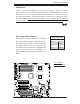
JPW2
J6
JPW1
JPL2
JPL1
JWD1
JI2C2
JPF
JI2C3
JI2C4
JI2C1
JP1
JWOR1
JL1
JOH1
JP3
JD1
FAN8
FAN4
FAN3
FAN7
FAN5
FAN2
LES2
LES1
LE1
DIMM1-1
DIMM1-2
DIMM0-3
DIMM1-3
DIMM0-2
DIMM0-1
SP1
CD1
JC2
J5
FAN6
JPW3
FAN1
JF1
I-button
Battery
BIOS
JWOL1
S I/O
Audio CTRL
LAN
LAN
CTRL
CTRL
Intel
5100
MCH
CPU1
CPU2
Intel
ICH9R
PXH-V
SAS0~3
SAS4~7
ITE
CTRL
X7DCA-i
SAS
CTRL
T-SGPIO2
IDE1
FLOPPY
USB4/5
USB6/7
I-SATA5
I-SATA4
I-SATA3
I-SATA2
I-SATA1
I-SATA0
USB9
CPU
COM2
USB
2/3
0/1/
USB8
J3P1
AUDIO
JAR
DIMM3A
DIMM3B
DIMM2A
DIMM2B
DIMM1B
DIMM1A
SLOT6 PCI-E X16
SLOT1 PCI-X 133/100MHz
SLOT2 PCI-X 133/100MHz
SLOT3 PCI 33MHz
SLOT4 PCI-E X4 (in X16 slot)
SLOT5 PCI 33MHz
SLOT7 SIMLP IPMI
LAN1/2
KB/MS
PRINTER
COM1
BANK3 BANK2
BANK1
FAN1
T-SGPIO1
JBT1
JPS1
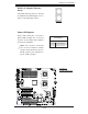
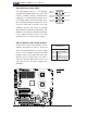
2-6 Jumper Settings
Explanation of
Jumpers
To modify the operation of the
motherboard, jumpers can be used
to choose between optional settings.
Jumpers create shorts between two pins
to change the function of the connector.
Pin 1 is identifi ed with a square solder
pad on the printed circuit board. See
the motherboard layout pages for jumper
locations.
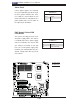
Note: On two pin jumpers, "Closed"
means the jumper is on and "Open"
means the jumper is off the pins.
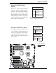
Connector
Pins
Jumper
Cap
Setting
Pin 1-2 short
3 2 1
3 2 1
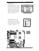
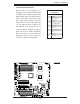
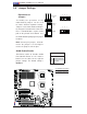
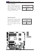
GLAN Enable/Disable
JPL1/JPL2 enable or disable GLAN
Port1/GLAN Port2 on the mother-
board. See the table on the right for
jumper settings. The default setting is
Enabled.
GLAN Enable
Pin# Defi nition
1-2 Enabled (default)
2-3 Disabled
A. GLAN Port1 Enable
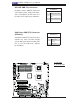
B. GLAN Port2 Enable
A
B