
User`s manual

Chapter 2: Installation
2-25
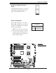
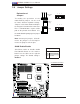
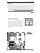
Front Panel Audio Control
When front panel headphones are
plugged in, the back panel audio output
is disabled. This is done through the FP
Audio header (JC2). If the front panel in-
terface card is not connected to the front
panel audio header, jumpers should be
installed on the header (JC2) pin pairs
1-2, 5-6, and 9-10. If these jumpers are
not installed, the back panel line out
connector will be disabled, and micro-
phone input Pin 1 will be left fl oating,
which can lead to excessive back panel
microphone noise and cross talk. See
the table at right for pin defi nitions.
HD Front Panel Audio
Pin Defi nitions
Pin# Signal
1 MIC_L
2 AUD_GND
3 MIC_R
4 FP_Audio-Detect
5 Line_2_R
6 Ground
7 FP_Jack-Detect
8 Key
9 Line_2_L
10 Ground
JPW2
J6
JPW1
JPL2
JPL1
JWD1
JI2C2
JPF
JI2C3
JI2C4
JI2C1
JP1
JWOR1
JL1
JOH1
JP3
JD1
FAN8
FAN4
FAN3
FAN7
FAN5
FAN2
LES2
LES1
LE1
DIMM1-1
DIMM1-2
DIMM0-3
DIMM1-3
DIMM0-2
DIMM0-1
SP1
CD1
JC2
J5
FAN6
JPW3
FAN1
JF1
I-button
Battery
BIOS
JWOL1
S I/O
Audio CTRL
LAN
LAN
CTRL
CTRL
Intel
5100
MCH
CPU1
CPU2
Intel
ICH9R
PXH-V
SAS0~3
SAS4~7
ITE
CTRL
X7DCA-i
SAS
CTRL
T-SGPIO2
IDE1
FLOPPY
USB4/5
USB6/7
I-SATA5
I-SATA4
I-SATA3
I-SATA2
I-SATA1
I-SATA0
USB9
CPU
COM2
USB
2/3
0/1/
USB8
J3P1
AUDIO
JAR
DIMM3A
DIMM3B
DIMM2A
DIMM2B
DIMM1B
DIMM1A
SLOT6 PCI-E X16
SLOT1 PCI-X 133/100MHz
SLOT2 PCI-X 133/100MHz
SLOT3 PCI 33MHz
SLOT4 PCI-E X4 (in X16 slot)
SLOT5 PCI 33MHz
SLOT7 SIMLP IPMI
LAN1/2
KB/MS
PRINTER
COM1
BANK3 BANK2
BANK1
FAN1
T-SGPIO1
JBT1
JPS1
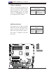
A
A. FP Audio