
User`s manual

2-24
X7DCA-3/X7DCA-i User's Manual
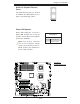
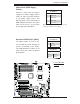
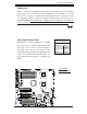
High Defi nition Audio (HDA)
This motherboard features a 7.1+2 Channel
High Defi nition Audio (HDA) (JC1) codec that
provides 10 DAC channels, simultaneously
supporting 7.1 sound playback and two chan-
nels of independent stereo sound output (mul-
tiple streaming) through the front panel stereo
out for the front L&R, rear L&R, center and
subwoofer speakers. This feature is activated
with an Advanced software included in the CD-
ROM that came with your motherboard. Sound
is then output through the Line In, Line Out
and MIC jacks (See at the picture at right.)
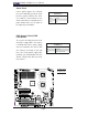
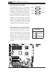
CD1
Pin Defi nitions
Pin# Defi nition
1 Left Stereo Signal
2 Ground
3 Ground
4 Right Stereo Signal
Grey: Side
Surround
Black: Back
Surround
Orange:
CEN/LFE
Pink: Mic-In
Green:Front
Blue: Line-In
CD and Auxiliary (FP) Audio Headers
A 4-pin CD header is located at CD1, and an
Auxiliary (Front Panel) header is located at
JC2 on the motherboard. These headers allow
you to use the onboard sound for audio CD
playback. Connect an audio cable from your
CD drive to the header that fi ts your cable's
connector. Only one CD header can be used
at any one time. See the tables at right for pin
defi nitions.
JPW2
J6
JPW1
JPL2
JPL1
JWD1
JI2C2
JPF
JI2C3
JI2C4
JI2C1
JP1
JWOR1
JL1
JOH1
JP3
JD1
FAN8
FAN4
FAN3
FAN7
FAN5
FAN2
LES2
LES1
LE1
DIMM1-1
DIMM1-2
DIMM0-3
DIMM1-3
DIMM0-2
DIMM0-1
SP1
CD1
JC2
J5
FAN6
JPW3
FAN1
JF1
I-button
Battery
BIOS
JWOL1
S I/O
Audio CTRL
LAN
LAN
CTRL
CTRL
Intel
5100
MCH
CPU1
CPU2
Intel
ICH9R
PXH-V
SAS0~3
SAS4~7
ITE
CTRL
X7DCA-i
SAS
CTRL
T-SGPIO2
IDE1
FLOPPY
USB4/5
USB6/7
I-SATA5
I-SATA4
I-SATA3
I-SATA2
I-SATA1
I-SATA0
USB9
CPU
COM2
USB
2/3
0/1/
USB8
J3P1
AUDIO
JAR
DIMM3A
DIMM3B
DIMM2A
DIMM2B
DIMM1B
DIMM1A
SLOT6 PCI-E X16
SLOT1 PCI-X 133/100MHz
SLOT2 PCI-X 133/100MHz
SLOT3 PCI 33MHz
SLOT4 PCI-E X4 (in X16 slot)
SLOT5 PCI 33MHz
SLOT7 SIMLP IPMI
LAN1/2
KB/MS
PRINTER
COM1
BANK3 BANK2
BANK1
FAN1
T-SGPIO1
JBT1
JPS1
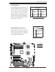
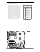
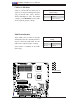
A
A. H.D Audio
B. CD1
B