
User`s manual

Chapter 2: Installation
2-23
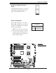
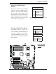
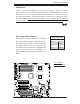
Power Fault (PWR Supply
Failure)
Connect a cable from your power
supply to the Power Supply Failure
header at J3P1 to provide warnings
of any power supply failure. This
warning signal is passed through the
PWR_LED pin to indicate of a power
failure on the chassis. See the table
on the right for pin defi nitions.
Note: This feature is only available when using
Supermicro redundant power supplies.
PWR Supply Failure
Pin Defi nitions
Pin# Defi nition
1 PWR 1: Fail
2 PWR 2: Fail
3 PWR 3: Fail
4 Signal: Alarm Reset
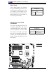
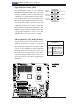
Overheat LED/Fan Fail (JOH1)
The JOH1 header is used to con-
nect an LED to provide warnings of
chassis overheating or fan failure.
This LED will blink to indicate a fan
failure. Refer to the table on right for
pin defi nitions.
Overheat LED
Pin Defi nitions
Pin# Defi nition
1 5vDC
2 OH Active
OH/Fan Fail LED
Pin Defi nitions
State Message
Solid Overheat
Blinking Fan Fail
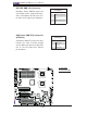
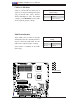
JPW2
J6
JPW1
JPL2
JPL1
JWD1
JI2C2
JPF
JI2C3
JI2C4
JI2C1
JP1
JWOR1
JL1
JOH1
JP3
JD1
FAN8
FAN4
FAN3
FAN7
FAN5
FAN2
LES2
LES1
LE1
DIMM1-1
DIMM1-2
DIMM0-3
DIMM1-3
DIMM0-2
DIMM0-1
SP1
CD1
JC2
J5
FAN6
JPW3
FAN1
JF1
I-button
Battery
BIOS
JWOL1
S I/O
Audio CTRL
LAN
LAN
CTRL
CTRL
Intel
5100
MCH
CPU1
CPU2
Intel
ICH9R
PXH-V
SAS0~3
SAS4~7
ITE
CTRL
X7DCA-i
SAS
CTRL
T-SGPIO2
IDE1
FLOPPY
USB4/5
USB6/7
I-SATA5
I-SATA4
I-SATA3
I-SATA2
I-SATA1
I-SATA0
USB9
CPU
COM2
USB
2/3
0/1/
USB8
J3P1
AUDIO
JAR
DIMM3A
DIMM3B
DIMM2A
DIMM2B
DIMM1B
DIMM1A
SLOT6 PCI-E X16
SLOT1 PCI-X 133/100MHz
SLOT2 PCI-X 133/100MHz
SLOT3 PCI 33MHz
SLOT4 PCI-E X4 (in X16 slot)
SLOT5 PCI 33MHz
SLOT7 SIMLP IPMI
LAN1/2
KB/MS
PRINTER
COM1
BANK3 BANK2
BANK1
FAN1
T-SGPIO1
JBT1
JPS1
A
A. SAS PWR SMB
B. Keylock
B