
User`s manual

2-20
X7DCA-3/X7DCA-i User's Manual
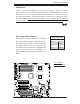
JPW2
J6
JPW1
JPL2
JPL1
JWD1
JI2C2
JPF
JI2C3
JI2C4
JI2C1
JP1
JWOR1
JL1
JOH1
JP3
JD1
FAN8
FAN4
FAN3
FAN7
FAN5
FAN2
LES2
LES1
LE1
DIMM1-1
DIMM1-2
DIMM0-3
DIMM1-3
DIMM0-2
DIMM0-1
SP1
CD1
JC2
J5
FAN6
JPW3
FAN1
JF1
I-button
Battery
BIOS
JWOL1
S I/O
Audio CTRL
LAN
LAN
CTRL
CTRL
Intel
5100
MCH
CPU1
CPU2
Intel
ICH9R
PXH-V
SAS0~3
SAS4~7
ITE
CTRL
X7DCA-i
SAS
CTRL
T-SGPIO2
IDE1
FLOPPY
USB4/5
USB6/7
I-SATA5
I-SATA4
I-SATA3
I-SATA2
I-SATA1
I-SATA0
USB9
CPU
COM2
USB
2/3
0/1/
USB8
J3P1
AUDIO
JAR
DIMM3A
DIMM3B
DIMM2A
DIMM2B
DIMM1B
DIMM1A
SLOT6 PCI-E X16
SLOT1 PCI-X 133/100MHz
SLOT2 PCI-X 133/100MHz
SLOT3 PCI 33MHz
SLOT4 PCI-E X4 (in X16 slot)
SLOT5 PCI 33MHz
SLOT7 SIMLP IPMI
LAN1/2
KB/MS
PRINTER
COM1
BANK3 BANK2
BANK1
FAN1
T-SGPIO1
JBT1
JPS1
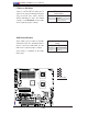
Alarm Reset
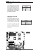
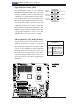
If three power supplies are installed,
the system will notify you when any of
the three power modules fails. Con-
nect JAR to a micro-switch to turn
off the alarm that is activated when a
power module fails. See the table on
the right for pin defi nitions.
Alarm Reset
Pin Defi nitions
Pin Setting Defi nition
Pin 1 Ground
Pin 2 +5V
A
A. Alarm Reset
B. PWR Fault
B
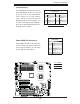
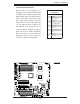
PWR Supply Failure/PWR
Fault Detect
The system can notify you in the event
of a power supply failure. This feature
is available when three power supply
units are installed in the chassis with
one acting as a backup. If you only
have one or two power supply units
installed, you should disable this (the
default setting) with JPF to prevent
false alarms.
PWR Supply PWR Fault
Pin Defi nitions
Jumper Setting Defi nition
On Enabled
Off Disabled (Default)