
User`s manual


2-26
X7DA8+/X7DAE+ User's Manual
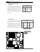
LAN1/2
®
S
UPER X7DA8+
Fan1
8-pin PWR
FP ControlSPK
PW LED
JOH1
Fan3
IDE1
Floppy
320 SCSI Channel A
Fan4
SATA3
SATA5
USB4/5
SMB
PCI-X 100 MHz ZCR (Green Slot)
PCI-X 133 MHz
JWD
Battery
GLAN
CTLR
JPG1
PCI-Exp x4
North Bridge
COM1
Fan6
Fan5
ATX PWR
4-Pin
PWR
J3P
24-Pin
SCSI CTRL
PXH
CPU1
CPU2
South Bridge
Fan7
JAR
J17
PSF
Fan2
Compact Flash
LE1
Fan8
JCF1
JWF1
JPA2
JPA3
JPA1
320 SCSI Channel B
SATA2
SATA4
SATA1
SATA0
JL1
PCI-X 133 MHz
JPL2
PCI-33MHz
FP Audio
PCI-Exp x16
SIM LP IPMI
DIMM 1A (Bank 1)
DIMM 1B (Bank 1)
DIMM 2A (Bank 2)
DIMM 2B (Bank 2)
DIMM 3A (Bank 3)
DIMM 3B (Bank 3)
DIMM 4A (Bank 4)
DIMM 4B (Bank 4)
JWOL
JWOR
KB/
Mouse
USB 0/
1/2/3
JI
2
C2
JI
2
C3
JI
2
C4
5000X
BIOS
DA1
DA2
CPU
Fan 1
CD1
JPL1
JI
2
C1
CPU
Fan2
HD
Audio
SGPIO1
SGPIO2
Parrallel
Port
Audio
CTRL
S I/O
J8
Clear
CMOS
ESB
Cha.
Intru.
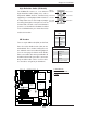
CMOS Clear
JBT1 is used to clear CMOS. Instead of pins, this "jumper" consists of contact pads
to prevent accidental clearing of CMOS. To clear CMOS, use a metal object such
as a small screwdriver to touch both pads at the same time to short the connection.
Always remove the AC power cord from the system before clearing CMOS. Note:
For an ATX power supply, you must completely shut down the system, remove the
AC power cord and then short JBT1 to clear CMOS.
A
B
A. Clear CMOS
B. Watch Dog Enable
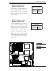
Watch Dog Enable/Disable
Watch Dog is a system monitor that can reboot
the system when a software application hangs.
Close pins 1-2 to reset the system if an applica-
tion hangs. Close pins 2-3 to generate a non-
maskable interrupt signal for the application that
hangs. See the table on the right for jumper set-
tings. Watch Dog must also be enabled in the
BIOS.
Watch Dog
Jumper Settings (JWD)
Jumper Setting Defi nition
Pins 1-2 Reset
(*default)
Pins 2-3 NMI
Open Disabled