
User`s manual


2-24
X7DA8+/X7DAE+ User's Manual
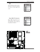
Front Panel Audio Control
When front panel headphones are plugged in, the back panel audio output is disabled.
This is done through the FP Audio header (J14). If the front panel interface card is
not connected to the front panel audio header, jumpers should be installed on the
header (J14) pin pairs: 1-2, 5-6, and 9-10. If these jumpers are not installed, the
back panel line out connector will be disabled and microphone input Pin 1 will be
left fl oating, which can lead to excessive back panel microphone noise and cross
talk. See the table below for pin defi nitions.
High Definition Front Panel Audio
Pins# Signal
1
MIC_L
2
AUD_GND
3
MIC_R
4
FP_Audio-Detect
5
Line_2_R
6
Ground
7
FP_Jack-Detect
8
Ke y
9
Line_2_L
10
Ground
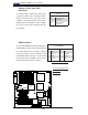
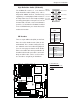
LAN1/2
®
S
UPER X7DA8+
Fan1
8-pin PWR
FP ControlSPK
PW LED
JOH1
Fan3
IDE1
Floppy
320 SCSI Channel A
Fan4
SATA3
SATA5
USB4/5
SMB
PCI-X 100 MHz ZCR (Green Slot)
PCI-X 133 MHz
JWD
Battery
GLAN
CTLR
JPG1
PCI-Exp x4
North Bridge
COM1
Fan6
Fan5
ATX PWR
4-Pin
PWR
J3P
24-Pin
SCSI CTRL
PXH
CPU1
CPU2
South Bridge
Fan7
JAR
J17
PSF
Fan2
Compact Flash
LE1
Fan8
JCF1
JWF1
JPA2
JPA3
JPA1
320 SCSI Channel B
SATA2
SATA4
SATA1
SATA0
JL1
PCI-X 133 MHz
JPL2
PCI-33MHz
FP Audio
PCI-Exp x16
SIM LP IPMI
DIMM 1A (Bank 1)
DIMM 1B (Bank 1)
DIMM 2A (Bank 2)
DIMM 2B (Bank 2)
DIMM 3A (Bank 3)
DIMM 3B (Bank 3)
DIMM 4A (Bank 4)
DIMM 4B (Bank 4)
JWOL
JWOR
KB/
Mouse
USB 0/
1/2/3
JI
2
C2
JI
2
C3
JI
2
C4
5000X
BIOS
DA1
DA2
CPU
Fan 1
CD1
JPL1
JI
2
C1
CPU
Fan2
HD
Audio
SGPIO1
SGPIO2
Parrallel
Port
Audio
CTRL
S I/O
J8
Clear
CMOS
ESB
Cha.
Intru.
A. FP Accessible Audio
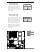
B. Alarm Reset
A
Alarm Reset
If three power supplies are installed
and Alarm Reset (JAR) is enabled, the
system will notify you when any of the
three power modules fails. Connect JAR
to a micro-switch to enable you to turn
off the alarm that is activated when a
power module fails. See the table on the
right for pin defi nitions.
Alarm Reset
Pin Setting Defi nition
Pin 1 Ground
Pin 2 +5V
B