
User`s manual


Chapter 1: Introduction
1-5
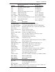
Jumper Description Default Setting
J3P 3rd PWR Failure Detect
Off (Disabled)
JAR Alarm Reset Off (Disabled)
JBT1 CMOS Clear See Chapter 2
JCF1 Compact Card Master/Slave Select On (Master)
JI
2
C1/JI
2
C2 SMB to PCI-X Slots Pins 2-3 (Disabled)
JI
2
C3/JI
2
C4 SMB to PCI-E Slots Pins 2-3 (Disabled)
JPA1 (*X7DA8+) SCSI Controller Enable Pins 1-2 (Enabled)
JPA2, JPA3 SCSI CHA(JPA2),CHB(JPA3)Term.En Off (Enabled) (*X7DA8+)
JPL1/ JPL2 GLAN1/GLAN2 Enable Pins 1-2 (Enabled)
JWD Watch Dog Pins 1-2 (Reset)
Connector Description
ATX PWR (JPW1) Primary 24-Pin ATX PWR Connector
Aux. PWR/CPU PWR +12V 4-pin PWR (JWP2)/+12V 8-pin PWR(JPW3)
HD Audio (JC1/JC2) Backplane HD Audio (JC1), Front Panel Audio (JC2)
CD-In (CD1) CD-In Header
Chassis Intrusion (JL1) Chassis Intrusion Header
COM1 COM1 Serial Port Connector
Compact PWR (JWF1) Compact Card PWR Connector
FAN 1-8 Fans 1-8 (Fan7: CPU Fan1, Fan8: CPU Fan2)
Floppy (J22) Floppy Disk Drive Connector
FP Control (JF1) Front Control Panel Connector
GLAN 1/2 (JLAN1) G-bit Ethernet Ports
IDE1/IDE2(Note) IDE1 Hard Drive (JIDE1)/Compact Flash Card (JIDE2)
Parallel (J21) Parallel (Printer) Port
PWR LED/SPKR (JD1) PWR LED(pins1-3)/SpeakerHeader (pins 4-7)
PWR SMB (J17) Power System Management (I
2
C) Header
PSF (JP3) Power Supply Failure (See Chapter 2)
SATA0-SATA5 Intel SATA 0-5 Connectors
SCSI (JA1/JA2) SCSI Channel A/Channel B Connectors (*X7DA8+)
SGPIO 1/2(J29,J30) Serial General Purpose Input/Output Headers
SMB (J18) System Management Bus Header
Slot 7 Low SIM Profi le IPMI Connector
USB 0/1/2/3/4/5 Back Panel USB 0/1/2/3(JUSB1), FP USB4/5 (JUSB2)
WOL (JWOL) Wake-on-LAN Header
WOR (JWOR) Wake-on-Ring Header
LED Indicators Description
DA1, DA2, SCSI Activity LED Indicators
LE1 5V Standby PWR LED Indicator
OH LED (JOH1) Overheat LED
Note: JIDE2 is for Compact Flash Card use only. Be sure to connect JWF1 to a
power supply to provide power to the Compact Flash Card.
Quick Reference (X7DA8+/X7DAE+)