
Datasheet


2-24
X6DHT-G User's Manual
LAN1
®
JLAN1
S
UPER X6DHT-G
LAN2
D
IM
M
2
A
D
IM
M
2
B
DIMM 3A
DIM
M
3B
DIMM 4A
DIMM 4B
DIMM 1B
D
IM
M
1
A
12V 8-pin
PWR
SMBus
PWR
JF1
FP Control
OH
LED
IP
M
I
IDE2
Floppy
C
O
M
2
B
IO
S
Fan4
S
A
TA
0
S
M
B
P
C
I-X
100 M
H
z
P
C
I-X
100 M
H
z/Z
C
R
P
C
I-X
3 133 M
H
z
B
attery
JPL1
R
A
G
E
-
X
L
P
C
I-E
X
8
Lindenhurst
N
orth
B
ridge
V
G
A
C
O
M
1
U
S
B
0/1
K
B
/
M
ouse
Fan6
F
an5
A
TX
P
W
R
12V 4-Pin
PWR
Parrallel
Port
24-P
in
Fan7
JPW1
Fan8
C
P
U
1
JWOR
S
I/O
PSF
Fan3
IDE1
P
C
I-32
U
SB
2/3
IC
H
JD
1
JP
G
1
JW
D
Slot1
Slot2
Slot3
Slot4
Slot5
Slot6
P
C
I-E
X
8
G
LA
N
C
T
LR
6300E
S
B
Buzzer
P
X
H
JB
T1
S
A
TA
1
S
A
T
A
0
S
A
T
A
1
S
A
T
A
2
S
A
T
A
3
S
A
T
A
4
S
A
T
A
5
S
A
T
A
6
S
A
T
A
7
M
arvell
Intel
G
LA
N
C
TLR
JPL2
M-SATA
Act LED
JL1
M-SATA
I
2
C
JPS1
S
A
T
A
C
ontroller
Fan2
Fan1
JAR
J3P
C
P
U
2
E
7520
Bank1
Bank2
Bank3
Bank4
WOL
D
S
9
D
S
1
D
S
1
0
D
S
2
D
S
11
D
S
3
D
S
1
2
D
S
4
D
S
13
D
S
5
D
S
14
D
S
6
D
S
15
D
S
7
D
S
16
D
S
8
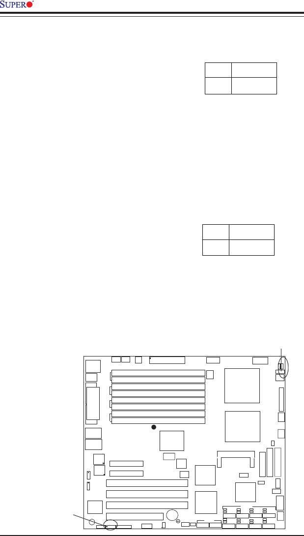
VGA Enable/Disable
JPG1 enables or disables the VGA
Connector on the motherboard.
See the table on the right for
jumper settings. The default set-
ting is enabled.
Jumper
Position
Pins 1-2
Pins 2-3
Definition
Enabled
Disabled
VGA
Enable/Disable
Jumper Settings
(JPG1)
Jumper
Position
2
1
Definition
+5V
Ground
Alarm Reset Jumper
Settings
(JAR)
Alarm Reset
The system will notify you in the
event of a power supply failure.
This feature assumes that Super-
micro redundant power supply
units are installed in the chassis.
If you only have a single power
supply installed, you should not
connect anything to this jumper to
prevent false alarms. See the
table on the right for jumper set-
tings.
VGA Enable
Alarm Reset