
Datasheet


Chapter 2: Installation
2-23
LAN1
®
J
L
A
N
1
S
UPER X6DHT-G
LAN2
DIMM 2A
D
IM
M
2
B
DIM
M
3A
D
IM
M
3
B
D
IM
M
4
A
D
IM
M
4
B
D
IM
M
1
B
DIMM 1A
12V 8-pin
PWR
SMBus
PWR
J
F
1
FP Control
OH
LED
IPMI
ID
E
2
F
lo
p
p
y
COM2
BIOS
Fan4
SATA0
SMB
P
C
I-X
1
00
M
H
z
P
C
I-X
1
0
0
M
H
z/Z
C
R
P
C
I-X
3
1
3
3
M
H
z
Battery
JP
L1
RAGE-
XL
P
C
I-E
X
8
Lindenhurst
North
Bridge
VGA
COM1
USB
0/1
KB/
Mouse
Fan6
Fan5
ATX PWR
12V 4-Pin
PW
R
Parrallel
Port
24-Pin
Fan7
JPW1
Fan8
CPU1
JWOR
S I/O
PSF
F
a
n
3
ID
E
1
P
C
I-3
2
USB2/3
ICH
JD1
JPG1
JWD
Slot1
Slot2
Slot3
Slot4
Slot5
Slot6
P
C
I-E
X
8
GLAN
CTLR
6300ESB
B
u
zzer
PXH
JBT1
SATA1
SATA0
SATA1
SATA2
SATA3
SATA4
SATA5
SATA6
SATA7
Marvell
Intel
GLAN
CTLR
JP
L
2
M-SATA
Act LED
JL1
M-SATA
I
2
C
JPS1
SATA
Controller
F
a
n
2
Fan1
J
A
R
J
3
P
CPU2
E7520
B
a
n
k
1
B
a
n
k
2
B
a
n
k
3
B
a
n
k
4
WOL
DS9
DS1
DS10
DS2
DS11
DS3
DS12
DS4
DS13
DS5
DS14
DS6
DS15
DS7
DS16
DS8
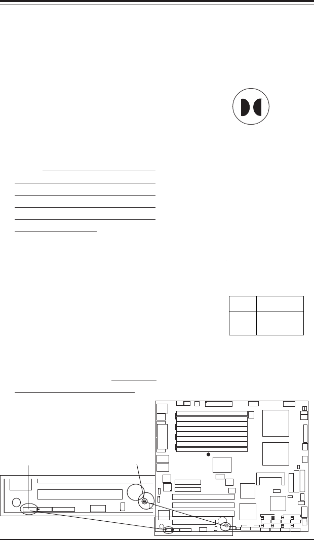
Watch Dog Enable
JWD controls Watch Dog, a system
monitor that takes action when a
software application freezes the
system. Pins 1-2 will have WD re-
set the system if a program
freezes. Pins 2-3 will generate a
non-maskable interrupt for the pro-
gram that has frozen (requires soft-
ware implementation). Watch Dog
must also be enabled in BIOS.
Jumper
Position
Pins 1-2
Pins 2-3
Open
Definition
WD to Reset
WD to NMI
Disabled
Watch Dog
Jumper Settings (JWD)
CMOS Clear
JBT1 is used to clear CMOS. In-
stead of pins, this "jumper" consists
of contact pads to prevent the ac-
cidental clearing of CMOS. To clear
CMOS, use a metal object such as
a small screwdriver to touch both
pads at the same time to short the
connection. Always remove the
AC power cord from the system
before clearing CMOS.
Note: For an ATX power supply,
you must completely shut down the
system, remove the AC power cord
and then short JBT1 to clear CMOS.
Do not use the PW_ON connec-
tor to clear CMOS.
Clear CMOS
Watch Dog Enable
COM2
SM
B
PCI-X100
MHz
Battery
XL
PCI-32
U
S
JD1
JPG1
JWD
Slot1
Buzzer
JBT1