
Datasheet


Chapter 2: Installation
2-19
LAN1
®
JLAN1
S
UPER X6DHT-G
LAN2
DIMM 2A
DIMM 2B
DIMM 3A
DIMM 3B
DIMM 4A
D
IM
M
4
B
DIM
M
1B
DIMM 1A
12V 8-pin
PWR
SMBus
PWR
JF1
FP Control
OH
LED
IPMI
ID
E
2
F
lo
p
p
y
COM2
BIOS
Fan4
SATA0
SMB
P
C
I-X
1
0
0
M
H
z
P
C
I-X
1
0
0 M
H
z/Z
C
R
P
C
I-X
3
13
3 M
H
z
Battery
JPL1
RAGE-
XL
P
C
I-E
X
8
Lindenhurst
North
Bridge
VGA
COM1
USB
0/1
KB/
Mouse
Fan6
Fan5
ATX PWR
12V 4-Pin
PW
R
Parrallel
Port
24-Pin
Fan7
JPW1
Fan8
CPU1
JWOR
S I/O
PSF
F
an3
ID
E
1
P
C
I-3
2
U
SB2/3
ICH
JD
1
JPG
1
JWD
Slot1
Slot2
Slot3
Slot4
Slot5
Slot6
P
C
I-E
X
8
GLAN
CTLR
6300ESB
Buzzer
PXH
JBT1
SATA1
SATA0
SATA1
SATA2
SATA3
SATA4
SATA5
SATA6
SATA7
M
arvell
Intel
GLAN
CTLR
JPL2
M-SATA
Act LED
JL1
M-SATA
I
2
C
JPS1
SATA
Controller
Fa
n
2
Fan1
JAR
J3P
CPU2
E7520
B
a
n
k
1
B
a
n
k
2
B
a
n
k
3
B
a
n
k
4
WOL
DS9
DS1
DS10
DS2
DS11
DS3
DS12
DS4
DS13
DS5
DS14
DS6
DS15
DS7
DS16
DS8
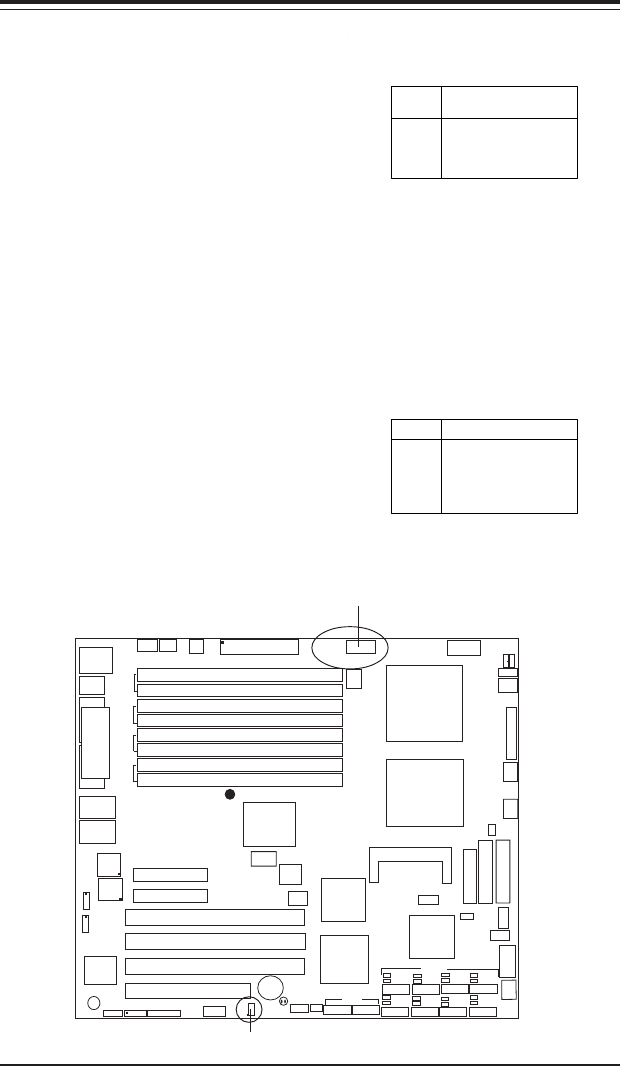
SMB
A System Management Bus
header is located at J11. Connect
the appropriate cable here to uti-
lize SMB on your system. See the
table on the right for pin defini-
tions.
SMB Power (I
2
C)
Connector
I
2
C Connector (J32), located be-
tween the 8-pin PWR Connector
and the 24-pin PWR Connector,
monitors the status of PWR Sup-
ply, Fan and system temperature.
See the table on the right for pin
definitions.
SMB PWR
Pin Definitions (J32)
Pin #
1
2
3
4
5
Definition
Clock
Data
N/A
N/A
N/A
SMB
SMB PWR
SMB Header
Pin Definitions (J11)
Pin
Number
1
2
3
4
Definition
Data
Ground
Clock
No Connection