
Datasheet


Chapter 2: Installation
2-15
LAN1
®
JL
A
N
1
S
UPER X6DHT-G
LAN2
DIMM 2A
DIMM 2B
D
IM
M
3A
DIMM 3B
DIMM 4A
DIMM 4B
D
IM
M
1
B
D
IM
M
1A
12V 8-pin
PWR
SMBus
PWR
JF
1
FP Control
OH
LED
IPMI
IDE2
Floppy
COM
2
BIOS
Fan4
SATA0
SMB
PCI-X100 M
Hz
PCI-X 100 MHz/ZCR
PCI-X 3 133 M
Hz
Battery
JPL1
RAGE-
XL
PCI-E X8
Lindenhurst
North
Bridge
VGA
COM1
USB
0/1
KB/
M
ouse
Fan6
Fan5
ATX PW
R
12V 4-Pin
PWR
Parrallel
Port
24-Pin
Fan7
JPW1
F
a
n8
CPU1
JWOR
S I/O
PSF
Fan3
IDE1
PCI-32
USB2/3
ICH
JD
1
JPG
1
JW
D
Slot1
Slot2
Slot3
Slot4
Slot5
Slot6
PCI-E X8
GLAN
CTLR
6300ESB
Buzzer
PXH
JBT1
SATA1
SATA0
SATA1
SATA2
SATA3
SATA4
SATA5
SATA6
SATA7
M
arvell
Intel
GLAN
CTLR
JPL2
M-SATA
Act LED
JL1
M-SATA
I
2
C
JPS1
SATA
Controller
Fan2
F
an1
JA
R
J3P
CPU2
E7520
Bank1
Bank2
Bank3
Bank4
WOL
DS9
DS1
DS10
DS2
DS11
DS3
DS12
DS4
DS13
DS5
DS14
DS6
DS15
DS7
DS16
DS8
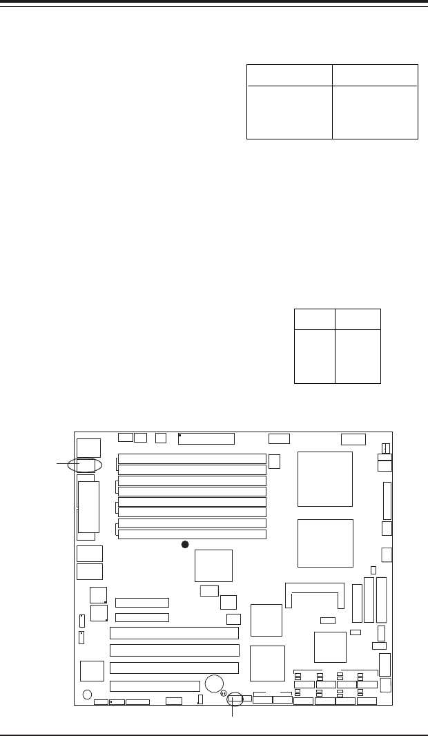
Front Panel Universal
Serial Bus Headers
Extra USB headers (FPUSB2/
FPUSB3) can be used for front
side USB access. You will need a
USB cable (eg. CBL-038) to use
either connection. Refer to the
tables on the right for pin defini-
tions.
Front Panel Universal
Serial Bus Pin Definitions
Pin
Number Definition
1+5V
2P0-
3P0+
4 Ground
5 N/A
FPUSB2/FPUSB3
Universal Serial Bus
(USB0/1)
Two USB 2.0 ports are located
beside the PS/2 keyboard/mouse
ports. USB0 is the bottom connec-
tor and USB1 is the top connector.
See the table on the right for pin
definitions.
Universal Serial Bus Pin Definitions
Pin
Number Definition
1+5V
2P0-
3P0+
4 Ground
5 N/A
Pin
Number Definition
1+5V
2P0-
3P0+
4 Ground
5Key
USB0
USB1
USB 0/1
FP USB 2/3