
Datasheet


Chapter 2: Installation
2-13
LAN1
®
JLAN1
S
UPER X6DHT-G
LAN2
DIMM 2A
D
IM
M
2B
D
IM
M
3
A
D
IM
M
3
B
D
IM
M
4
A
D
IM
M
4
B
D
IM
M
1
B
DIMM 1A
12V 8-pin
PWR
SMBus
PWR
JF1
FP Control
OH
LED
IP
M
I
IDE2
Floppy
C
O
M
2
B
IO
S
Fan4
S
A
T
A
0
S
M
B
P
C
I-X
1
0
0
M
H
z
P
C
I-X
1
0
0
M
H
z
/Z
C
R
P
C
I-
X
3
1
3
3
M
H
z
B
a
tte
ry
JP
L1
R
A
G
E
-
X
L
P
C
I-E
X
8
L
in
d
e
n
h
u
rs
t
N
o
rth
B
rid
g
e
V
G
A
C
O
M
1
U
S
B
0
/1
K
B
/
M
o
u
s
e
F
a
n
6
F
a
n
5
A
T
X
P
W
R
1
2
V
4
-P
in
P
W
R
Parrallel
Port
2
4
-P
in
F
a
n
7
JPW1
Fan8
C
P
U
1
JWOR
S
I/O
PSF
F
a
n
3
IDE1
P
C
I-
3
2
U
S
B
2
/3
IC
H
J
D
1
J
P
G
1
J
W
D
S
lot1
S
lot2
S
lot3
S
lot4
S
lot5
S
lot6
P
C
I-E
X
8
G
L
A
N
C
T
L
R
6
3
0
0
E
S
B
Buzzer
P
X
H
J
B
T
1
S
A
T
A
1
S
A
T
A
0
S
A
T
A
1
S
A
T
A
2
S
A
T
A
3
S
A
T
A
4
S
A
T
A
5
S
A
T
A
6
S
A
T
A
7
M
a
rv
e
ll
In
te
l
G
L
A
N
C
T
L
R
JP
L2
M-SATA
Act LED
JL1
M-SATA
I
2
C
JPS1
S
A
T
A
C
o
n
tro
lle
r
F
a
n
2
Fan1
JAR
J3P
C
P
U
2
E
7
5
2
0
B
a
n
k
1
B
a
n
k
2
B
a
n
k
3
B
a
n
k
4
WOL
D
S
9
D
S
1
D
S
1
0
D
S
2
D
S
1
1
D
S
3
D
S
1
2
D
S
4
D
S
1
3
D
S
5
D
S
1
4
D
S
6
D
S
1
5
D
S
7
D
S
1
6
D
S
8
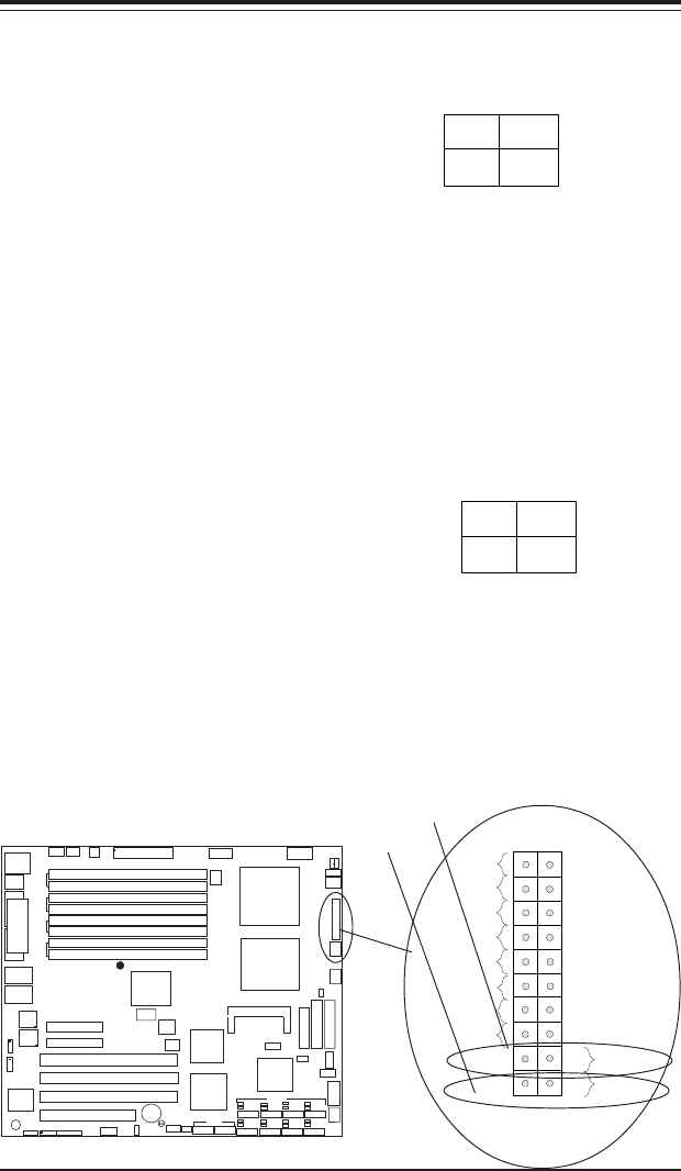
Power Button
The Power Button connection is
located on pins 1 and 2 of JF1.
Momentarily contacting both pins
will power on/off the system. This
button can also be configured to
function as a suspend button
(with a setting in BIOS - see Chap-
ter 4). To turn off the power
when set to suspend mode, de-
press the button for at least 4
seconds. Refer to the table on the
right for pin definitions.
Pin
Number
1
2
Definition
PW_ON
Ground
Power Button
Connector
Pin Definitions
(JF1)
Reset Button
The Reset Button connection is lo-
cated on pins 3 and 4 of JF1. At-
tach it to the hardware reset
switch on the computer case.
Refer to the table on the right for
pin definitions.
Pin
Number
3
4
Definition
Reset
Ground
Reset Pin
Definitions
(JF1)
Power Button
Overheat LED
1
NIC1 LED
Reset Button
2
Power Fail LED
HDD LED
Power LED
Reset
Pwr
Vcc
Vcc
Vcc
Vcc
Ground
Ground
1920
Vcc
X
Ground
NMI
X
NIC2 LED
Vcc
Reset Button
PWR Button