
Datasheet


Chapter 2: Installation
2-9
LAN1
®
JLAN1
S
UPER X6DHT-G
LAN2
DIMM 2A
DIMM 2B
D
IM
M
3
A
D
IM
M
3
B
D
IM
M
4A
D
IM
M
4
B
D
IM
M
1
B
DIMM 1A
12V 8-pin
PWR
SMBus
PWR
JF
1
FP Control
OH
LED
IPMI
IDE2
F
lo
p
p
y
COM2
BIOS
Fan4
SATA0
SMB
PCI-X100 MHz
PCI-X 100 MHz/ZCR
PCI-X 3 133 MHz
Battery
JPL1
RAGE-
XL
PCI-E X8
Lindenhurst
North
Bridge
VGA
COM1
USB
0/1
KB/
Mouse
Fan6
Fan5
ATX PWR
12V 4-Pin
PW
R
Parrallel
Port
24-Pin
Fan7
JPW1
F
a
n
8
CPU1
JWOR
S I/O
PSF
Fan3
IDE1
PCI-32
U
S
B
2
/3
ICH
J
D
1
J
P
G
1
JWD
Slot1
Slot2
Slot3
Slot4
Slot5
Slot6
PCI-E X8
GLAN
CTLR
6300ESB
B
u
z
z
e
r
PXH
JB
T
1
SATA1
SATA0
SATA1
SATA2
SATA3
SATA4
SATA5
SATA6
SATA7
M
a
rv
e
ll
In
te
l
GLAN
CTLR
JPL2
M-SATA
Act LED
JL1
M-SATA
I
2
C
JPS1
SATA
Controller
Fan2
F
a
n
1
JA
R
J
3P
CPU2
E7520
B
a
n
k1
B
an
k2
B
an
k3
B
a
n
k4
WOL
DS9
DS1
DS10
DS2
DS11
DS3
DS12
DS4
DS13
DS5
DS14
DS6
DS15
DS7
DS16
DS8
ATX Power Supply 24-pin Connector
Pin Definitions(JPW1)
Pin Number Definition
13 +3.3V
14 -12V
15 COM
16 PS_ON#
17 COM
18 COM
19 COM
20 Res(NC)
21 +5V
22 +5V
23 +5V
24 COM
Pin Number Definition
1 +3.3V
2 +3.3V
3 COM
4 +5V
5 COM
6 +5V
7 COM
8 PWR_OK
9 5VSB
10 +12V
11 +12V
12 +3.3V
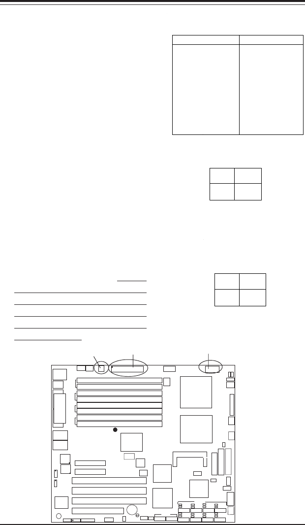
2-5 Connecting Cables
ATX Power Connector
The main power supply connector
(JPW1) on the X6DHT-G meets the
SSI (Superset ATX) specification.
You can only use a 24-pin power
supply cable on the motherboard.
Make sure that the orientation of
the connector is correct. You
must also use the 4-pin (J38)
power connector for adequate
power supply to the system. See
the table on the right for pin defini-
tions.
Pins
1 thru 4
5 thru 8
Definition
Ground
+12v
8-Pin +12v Power Supply
Connector (J1D1)
Processor Power
Connector
In addition to the Primary ATX
power connector (above), the 12v
8-pin Processor connector at J1D1
must also be connected to your
power supply for CPU power con-
sumption to avoid causing instabil-
ity to the system.
Pins #
1 & 2
3 & 4
Definition
Ground
+12 V
+12V 4-pin
Connector
(J38)
24-Pin ATX PWR 8-Pin 12V PWR
4-Pin12V CPU PWR