
User`s manual

Chapter 2: Installation
2-19
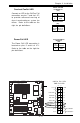
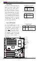
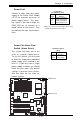
Power Fault
Connect a cable from your power
supply to the Power Fault header
(JP12) to provide warnings of
power supply failure. This warn-
ing signal is passed through the
PWR_LED pin to indicate of a
power failure on the chassis. See
the table on the right for pin defini-
tions.
Power Fault
Pin Definitions (JP12)
Pin
Number
1
2
3
4
Definition
PWR 1 Fail Signal
PWR 2 Fail Signal
PWR 3 Fail Signal
Signal: Alarm Reset
Note: This feature is only available when using
redundant Supermicro power supplies.
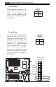
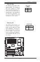
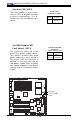
Power Fail Alarm Clear
Switch (Alarm Reset)
The system will notify you in the
event of a power supply failure.
To use this feature, you will need
to have the Supermicro redundant
power supply units installed in the
chassis. If you only have a single
power supply installed, you should
leave the pins open (the default
setting) to prevent false alarms.
See the table on the right for
jumper settings.
Jumper
Position
Open
Short
Definition
Normal(*default
)
Clear Alarm
Alarm Clear Switch
(JP14)
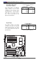
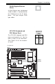
GLAN1
®
S
UPER X6DH8-XG2
GLAN2
D
IM
M
2
B
(B
a
n
k
2
)
D
IM
M
2
A
(B
a
n
k
2
)
D
IM
M
3
B
(B
a
n
k
3
)
D
IM
M
3
A
(B
a
n
k
3
)
D
IM
M
4
B
(B
a
n
k
4
)
D
IM
M
4
A
(B
a
n
k
4
)
D
IM
M
1
A
(B
a
n
k
1
)
D
IM
M
1
B
(B
a
n
k
1
)
Fan1
8-pin
PWR
PWR
SMBus
C
P
U
F
a
n
1
JF1
F
P
C
o
n
tr
o
l
JD1
SPK
PW LED
J
P
1
5
Fan2
OH
3rd PS
PWR
Fault
Detect
C
P
U
F
a
n
2
Fan3
C
H
In
tru
J
L
1
W
D
E
n
a
b
le
IP
M
I
IDE1
ID
E
2
Floppy
B
IO
S
J
1
8
J
P
A
1
Ultra 320
SCSI CH A
Ultra 320
SCSI CH B
Fan4
7
9
0
2
C
T
R
L
S
A
T
A
0
S
A
T
A
1
U
S
B
2
/3
S
M
B
U
S
B
u
z
z
e
r
PCI-X 1 100 MHz ZCR
PCI-X 2 100 MHz
PCI-X #3 133 MHz
WOR
B
a
tte
ry
J
P
L
1
G
L
A
N
C
T
L
R
R
A
G
E
-X
8
2
5
4
6
G
L
A
N
E
n
a
b
le
PCI-X #5 133MHz
X8 PCI-Epx #6
S
u
p
er
I/O
(N
o
rth
B
rid
g
e
)
J
P
G
1
V
G
A
C
O
M
1
U
S
B
0
/1
K
B
/
M
o
u
s
e
F
a
n
5
F
a
n
6
A
T
X
P
W
R
4
-P
in
P
W
R
JP16
2
4
-P
in
Force PWR ON
V
G
A
E
n
a
b
le
F
a
n
7
J24
J
P
1
2
Reboot
Option
JP14
J
P
1
3
F
a
n
8
SCSI
C
P
U
1
C
P
U
2
A
la
rm
R
e
se
t
SCSI
Enable
P
X
H
PCI-X #4 133MHz
C
O
M
2
W
O
L
U
S
B
4
P
W
R
F
a
u
lt
LE1
P
W
L
E
D
J
P
A
2
J
P
A
3
DA1
DA2
IC
H
5
R
P
X
H
Lindenhurst
Clear
CMOS
CHB SCSI LED
CHA SCSI LED
(S
o
u
th
B
rid
g
e
)
E
75
2
0
82
80
1
E
R
SCSI CH A Term
SCSI CH B Term
PWR Fault
Alarm Reset