
User`s manual

2-18
X6DH8-XG2/X6DHE-XG2 User's Manual
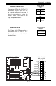
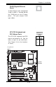
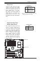
SMB
A System Management Bus
header is located at J22. Connect
the appropriate cable here to uti-
lize SMB on your system.
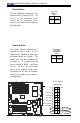
Fan Header Pin Definitions
Pin
Number
1
2
3
4
Definition
Date
Ground
Clock
NA
Caution: These fan headers
are DC power.
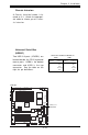
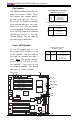
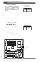
SMB Power (I
2
C)
Connector
I
2
C Connector (J24), located be-
tween Fan7 (CPU1 Fan), and the
PWR Fault header, monitors the
status of PWR Supply, Fan and
system temperature.
SMB PWR
Pin Definitions (J24)
Pin #
1
2
3
4
5
Definition
Clock
Data
N/A
GND
+3.3V
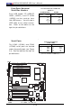
GLAN1
®
S
UPER X6DH8-XG2
GLAN2
DIMM 2B (Bank 2)
DIMM 2A (Bank 2)
DIMM 3B (Bank 3)
DIMM 3A (Bank 3)
DIMM 4B (Bank 4)
DIMM 4A (Bank 4)
DIMM 1A (Bank 1)
DIMM 1B (Bank 1)
Fan1
8-pin
PWR
PWR
SMBus
C
P
U
Fan1
JF1
F
P
C
o
n
tr
o
l
J
D
1
S
P
K
PW LED
J
P
1
5
Fan2
OH
3rd PS
PWR
Fault
Detect
C
P
U
F
an2
Fan3
C
H
Intru
JL1
W
D
E
n
able
IP
M
I
IDE1
IDE2
F
lo
p
p
y
B
IO
S
J
1
8
JP
A
1
Ultra 320
S
C
S
I C
H
A
Ultra 320
SCSI CH B
F
a
n
4
7902
C
TR
L
S
A
T
A
0
S
A
T
A
1
U
S
B
2/3
S
M
B
U
S
B
uzzer
PCI-X 1 100 MHz ZCR
PCI-X 2 100 MHz
PCI-X #3 133 MHz
WOR
B
attery
JP
L
1
G
LA
N
C
TLR
R
A
G
E
-X
82546
G
LA
N
E
nab
le
PCI-X #5 133MHz
X8 PCI-Epx #6
Super
I/O
(N
o
rth
B
ridge)
JP
G
1
V
G
A
C
O
M
1
U
SB
0/1
K
B
/
M
ouse
F
an5
F
an6
A
TX
PW
R
4-P
in
P
W
R
JP16
24-P
in
Force PWR ON
V
G
A
E
n
ab
le
Fan7
J24
JP12
R
e
b
o
o
t
O
p
tio
n
JP14
J
P
1
3
F
a
n
8
SCSI
C
P
U
1
C
P
U
2
A
la
r
m
R
e
s
e
t
SCSI
Enable
P
X
H
PCI-X #4 133MHz
C
O
M
2
W
O
L
U
S
B
4
PWR
Fault
LE1
P
W
L
E
D
JP
A
2
JP
A
3
DA1
D
A
2
IC
H
5R
P
X
H
Lindenhurst
Clear
CMOS
C
H
B
S
C
S
I L
E
D
C
H
A
S
C
S
I L
E
D
(South
B
ridg
e)
E7520
82801ER
S
C
S
I C
H
A
T
e
rm
S
C
S
I C
H
B
T
e
rm
SMB PWR
SMB