
User`s manual

Chapter 2: Installation
2-17
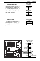
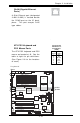
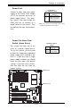
Wake-On-Ring
The Wake-On-Ring header is des-
ignated JWOR1. This function al-
lows your computer to receive
and to be awakened up by an in-
coming call to the modem when in
suspend state. See the table on
the right for pin definitions. You
must have a Wake-On-Ring card
and cable to use this feature.
Wake-on-Ring
Pin Definitions
(JWOR1)
Pin
Number
1
2
Definition
Ground
Wake-up
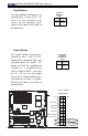
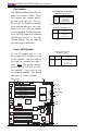
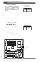
Wake-On-LAN
The Wake-On-LAN header is lo-
cated at JWOL on the mother-
board. See the table on the right
for pin definitions. You must en-
able LAN Wake-Up in the BIOS to
use this function. (You must also
have a LAN card with a Wake-On-
LAN connector and cable to use
this feature.)
Pin
Number
1
2
3
Definition
+5V Standby
Ground
Wake-up
Wake-On-LAN Pin
Definitions (JWOL)
GLAN1
®
S
UPER X6DH8-XG2
GLAN2
DIMM 2B (Bank 2)
DIMM 2A (Bank 2)
DIMM 3B (Bank 3)
DIMM 3A (Bank 3)
DIMM 4B (Bank 4)
DIMM 4A (Bank 4)
DIMM 1A (Bank 1)
DIMM 1B (Bank 1)
Fan1
8-pin
PWR
PWR
SMBus
C
P
U
F
a
n
1
JF1
F
P
C
o
n
tr
o
l
JD
1
S
P
K
PW LED
JP15
Fan2
OH
3rd PS
PWR
Fault
Detect
C
P
U
F
a
n
2
Fan3
C
H
In
t
r
u
J
L
1
W
D
E
n
a
b
le
IP
M
I
IDE1
ID
E
2
F
lo
p
p
y
B
IO
S
J18
J
P
A
1
Ultra 320
SCSI CH A
Ultra 320
SCSI CH B
Fan4
7
9
0
2
C
T
R
L
S
A
T
A
0
S
A
T
A
1
U
S
B
2
/3
S
M
B
U
S
B
u
z
z
e
r
PCI-X 1 100 MHz ZCR
PCI-X 2 100 MHz
PCI-X #3 133 MHz
WOR
B
a
tt
e
r
y
J
P
L
1
G
L
A
N
C
T
L
R
R
A
G
E
-X
8
2
5
4
6
G
L
A
N
E
n
a
b
le
PCI-X #5 133MHz
X8 PCI-Epx #6
S
u
p
e
r
I/O
(N
o
r
t
h
B
r
id
g
e
)
J
P
G
1
V
G
A
C
O
M
1
U
S
B
0
/1
K
B
/
M
o
u
s
e
F
a
n
5
F
a
n
6
A
T
X
P
W
R
4
-
P
in
P
W
R
JP16
2
4
-
P
in
Force PWR ON
V
G
A
E
n
a
b
le
F
a
n
7
J24
JP12
R
e
b
o
o
t
O
p
tio
n
JP14
J
P
1
3
F
a
n
8
SCSI
C
P
U
1
C
P
U
2
A
la
r
m
R
e
s
e
t
SCSI
Enable
P
X
H
PCI-X #4 133MHz
C
O
M
2
W
O
L
U
S
B
4
P
W
R
F
a
u
lt
LE1
P
W
L
E
D
J
P
A
2
J
P
A
3
DA1
D
A
2
IC
H
5
R
P
X
H
Lindenhurst
Clear
CMOS
C
H
B
S
C
S
I L
E
D
C
H
A
S
C
S
I L
E
D
(S
o
u
th
B
r
id
g
e
)
E
7
5
2
0
8
2
8
0
1
E
R
S
C
S
I C
H
A
T
e
r
m
S
C
S
I C
H
B
T
e
r
m
WOR
WOL