
User`s manual

Chapter 2: Installation
2-15
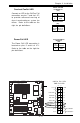
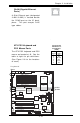
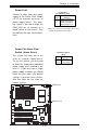
ATX PS/2 Keyboard and
PS/2 Mouse Ports
The ATX PS/2 keyboard and PS/2
mouse are located at J9. See the
table at right for pin definitions.
(See Figure 2-3 for the locations
of each.)
PS/2 Keyboard
and Mouse Port
Pin Definitions
(JKM1)
Pin
Number
1
2
3
4
5
6
Definition
Data
NC
Ground
VCC
Clock
NC
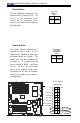
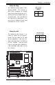
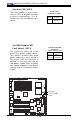
GLAN (Giga-bit Ethernet
Ports)
A G-bit Ethernet port (designated
JLAN1/JLAN2) is located beside
the COM2 port on the IO back-
plane. This port accepts RJ45
type cables.
GLAN1
®
S
UPER X6DH8-XG2
GLAN2
DIM
M
2B (Bank 2)
DIM
M
2A (Bank 2)
DIM
M
3B (Bank 3)
DIM
M
3A (Bank 3)
DIM
M
4B (Bank 4)
DIM
M
4A (Bank 4)
DIM
M
1A (Bank 1)
DIM
M
1B (Bank 1)
Fan1
8-pin
PWR
PWR
SMBus
C
P
U
F
a
n
1
JF1
F
P
C
o
n
tr
o
l
JD1
S
P
K
PW LED
J
P
1
5
Fan2
OH
3rd PS
PWR
Fault
Detect
C
P
U
F
a
n
2
Fan3
C
H
In
tru
J
L
1
W
D
E
n
a
b
le
IP
M
I
IDE1
ID
E
2
F
lo
p
p
y
B
IO
S
J18
J
P
A
1
Ultra 320
SCSI CH A
U
ltra
3
2
0
S
C
S
I C
H
B
Fan4
7
9
0
2
C
T
R
L
S
A
T
A
0
S
A
T
A
1
U
S
B
2
/3
S
M
B
U
S
B
u
zz
e
r
P
C
I-X
1
1
0
0
M
H
z
Z
C
R
P
C
I-X
2
1
0
0
M
H
z
P
C
I-X
#
3
1
3
3
M
H
z
W
O
R
B
atte
ry
J
P
L
1
G
L
A
N
C
T
L
R
R
A
G
E
-X
8
2
5
4
6
G
L
A
N
E
n
a
b
le
P
C
I-X
#
5
1
3
3
M
H
z
X
8
P
C
I-E
p
x
#
6
Super
I/O
(N
o
rth
B
rid
g
e
)
J
P
G
1
V
G
A
C
O
M
1
U
S
B
0
/1
K
B
/
M
o
u
s
e
F
a
n
5
F
an
6
A
T
X
P
W
R
4
-P
in
P
W
R
JP16
2
4
-P
in
Force PWR ON
V
G
A
E
n
ab
le
F
a
n
7
J24
J
P
1
2
R
ebo
o
t
O
p
tio
n
JP14
JP13
F
a
n
8
SCSI
C
P
U
1
C
P
U
2
A
la
rm
R
e
s
et
SCSI
Enable
P
X
H
P
C
I-X
#
4
1
3
3
M
H
z
C
O
M
2
W
O
L
U
S
B
4
P
W
R
F
a
u
lt
L
E
1
PW
LED
J
P
A
2
J
P
A
3
DA1
D
A
2
IC
H
5R
P
X
H
L
in
d
e
n
h
u
rs
t
Clear
CMOS
C
H
B
S
C
S
I L
E
D
C
H
A
S
C
S
I L
E
D
(S
o
u
th
B
rid
g
e
)
E7520
82801ER
S
C
S
I C
H
A
T
erm
S
C
S
I C
H
B
T
erm
Keyboard/
Mouse
GLAN1
GLAN2