
User`s manual

2-8
X6DH8-XG2/X6DHE-XG2 User's Manual
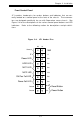
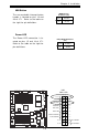
ATX Power Supply 24-pin Connector
Pin Definitions (JPW1)
Pin Number Definition
13 +3.3V
14 -12V
15 COM
16 PS_ON#
17 COM
18 COM
19 COM
20 Res(NC)
21 +5V
22 +5V
23 +5V
24 COM
Pin Number Definition
1 +3.3V
2 +3.3V
3 COM
4 +5V
5 COM
6 +5V
7 COM
8 PWR_OK
9 5VSB
10 +12V
11 +12V
12 +3.3V
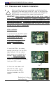
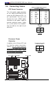
2-5 Connecting Cables
ATX Power Connector
The main power supply connector
on the X6DH8-XG2/X6DHE-XG2
meets the SSI (Superset ATX) 24-
pin specification. You must also
connect the 4-pin (JPW2) power
connector to your power supply to
provide adequate power supply
for system power consumption.
See the table on the right for pin
definitions.
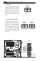
Pins
1 thru 4
5 thru 8
Definition
Ground
+12v
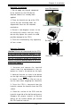
+12v 8-Pin Power Supp
ly
Connector (J1D1)
Processor Power
Connector
In addition to the Primary ATX and
the Auxiliary power connectors
(above), the 12v 8-pin Processor
connector at JPW3 must also be
connected to your power supply
for CPU power consumption.
Pins #
1 & 2
3 & 4
Definition
Ground
+12 V
+12V 4-pin
Connector
(JPW2)
GLAN1
®
S
U
P
E
R
X
6
D
H
8
-X
G
2
GLAN2
D
IM
M
2
B
(B
a
n
k
2
)
D
IM
M
2
A
(B
a
n
k
2
)
D
IM
M
3
B
(B
a
n
k
3
)
D
IM
M
3
A
(B
a
n
k
3
)
D
IM
M
4
B
(B
a
n
k
4
)
D
IM
M
4
A
(B
a
n
k
4
)
D
IM
M
1
A
(B
a
n
k
1
)
D
IM
M
1
B
( B
a
n
k
1
)
Fa n1
8-p in
PWR
PWR
SMBus
CPU
Fa n1
JF1
F
P
C
o
n
tr
o
l
JD
1
S
P
K
PW LED
JP 15
Fa n2
OH
3rd PS
PWR
Fau lt
Detect
CPU Fan 2
Fa n3
CH Int ru
JL1
WD Enable
IPMI
IDE1
ID
E
2
F
lo
p
p
y
BIOS
J18
JP A1
Ul tra 32 0
S
C
S
I C
H
A
U
lt
r
a
3
2
0
S
C
S
I
C
H
B
F
a
n
4
79 02
CT RL
SAT A0
SAT A1
USB 2/3
SMBUS
Bu zze r
P
C
I-X
1
1
0
0
M
H
z
Z
C
R
P
C
I-
X
2
1
0
0
M
H
z
P
C
I-X
#
3
1
3
3
M
H
z
WOR
Bat tery
JPL 1
GL AN
CT LR
RAGE-X
82 54 6
GL AN
Enable
P
C
I-X
#
5
1
3
3
M
H
z
X
8
P
C
I-
E
p
x
#
6
Super
I/O
(N ort h
Bri dge)
JPG 1
VGA
C
O
M
1
U
S
B
0/1
KB/
Mous e
Fa n5
Fa n6
ATX PWR
4-Pin
PWR
JP 16
24-P in
For ce PWR ON
VGA
Enable
Fa n7
J24
J
P
1
2
Reboot
Option
JP 14
J
P
13
Fa n8
SCSI
CPU 1
CPU 2
A
la
rm
R
e
s
et
SCSI
Enable
PXH
P
C
I-X
#
4
1
3
3
M
H
z
CO M2
WOL
US B4
P
W
R
F
a
u
lt
LE1
PW LED
JP A2
JP A3
DA 1
D
A
2
IC H5R
PXH
L
in
d
e
n
h
u
r
s
t
Clear
CMOS
C
H
B
S
C
S
I L
E
D
C
H
A
S
C
S
I L
E
D
(Sou th
Bri dge)
E7520
82801ER
S
C
S
I C
H
A
T
e
rm
S
C
S
I C
H
B
T
e
rm
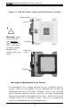
24-pinPWR
8-Pin PWR
(*Required)
(*
Required)
4-Pin PWR