
User`s manual


Chapter 2: Installation
2-29
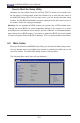
Main Power LED
A Main Power LED is located at LED1
on the motherboard. When this LED is
on, the system power is on. Be sure to
turn off the system power and unplug the
power cord before removing or installing
components. See the table on the right for
more information.
Main PWR LED Indicator
LED Settings
LED Color Denition
Off System Off (PWR cable
not connected)
Green System Power On
Green:
Flashing
Quickly
ACPI S1 State
Standby Power LED
The 5V Standby Power LED is located at
LED5 on the motherboard. When this LED
is on, the standby power is connected. Be
sure to unplug the power cable before
removing or installing components. See
the table in the right for more information.
Standby PWR LED Indicator
LED Settings
LED Color Denition
Off 5V Standby Power Off
(PWR cable not con-
nected)
Green Standby PWR Cable
Connected
X10SBA(-L)
Rev.
1.01A
JSMB1
J31
JBT1
BT2
M-SATA0M-SATA1
M-SATA2
M-SATA3
JP1
LAN1LAN2
JDIMM2
PJ1
JF1
JTPM1
JOH1
JSPDIF_OUT
JPUSB1
JPAC1
JPME2
JD1
VGA
FAN1
FAN2
I-SATA1
COM4
COM2
SP1
JSD1
JDIMM1
LED3
LED4
LED2
JPW1
SMBUS1
SLOT1 PCI-E 2.0 X2 (IN X8)
USB4/5
USB6
AUDIO FP
SODIMM2 (1.35V only)
USB1(2.0)
USB0(3.0)
CPU
(Install first)SODIMM1(1.35V only)
eDP
Non-ECC DDR3 Required
HDMI/DP
COM3
FP CTRL
BIOS
BAR CODE
J1
(for mini-PCI-E only)
(for M-SATA only)
J2
COM1
(for X10SBA only)
(for X10SBA only)
(for X10SBA only)
(for X10SBA)
LED1
LED5
USB2/3
I-SATA0
A. Main PWR LED
B. Standby PWR
LED
A
B