
User`s manual


2-28
X10SBA/X10SBA-L User’s Manual
X10SBA(-L)
Rev.
1.01A
JSMB1
J31
JBT1
BT2
M-SATA0M-SATA1
M-SATA2
M-SATA3
JP1
LAN1LAN2
JDIMM2
PJ1
JF1
JTPM1
JOH1
JSPDIF_OUT
JPUSB1
JPAC1
JPME2
JD1
VGA
FAN1
FAN2
I-SATA1
COM4
COM2
SP1
JSD1
JDIMM1
LED3
LED4
LED2
JPW1
SMBUS1
SLOT1 PCI-E 2.0 X2 (IN X8)
USB4/5
USB6
AUDIO FP
SODIMM2 (1.35V only)
USB1(2.0)
USB0(3.0)
CPU
(Install first)SODIMM1(1.35V only)
eDP
Non-ECC DDR3 Required
HDMI/DP
COM3
FP CTRL
BIOS
BAR CODE
J1
(for mini-PCI-E only)
(for M-SATA only)
J2
COM1
(for X10SBA only)
(for X10SBA only)
(for X10SBA only)
(for X10SBA)
LED1
LED5
USB2/3
I-SATA0
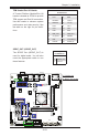
A. LAN 1/2 LED
LAN 1/LAN 2 LEDs
Two LAN ports (LAN 1/LAN 2) are located
on the I/O backplane of the motherboard.
Each Ethernet LAN port has two LEDs. The
yellow LED indicates activity, while the Link
LED may be green, amber, or off to indicate
the speed of the connections. See the
tables at right for more information.
2-8 Onboard Indicators
LAN1 LAN2
Activity LED
Link LED
GLAN Ports 1/2 Link Indicator
LED Settings
LED Color Denition
Off No Connection/10 Mbps
Amber 1 Gbps
Green 100 Mbps
GLAN 1/2 Activity Indicator
LED Settings
Color Status Denition
Yellow Flashing Active
A
A