
User`s manual


2-26
X10SBA/X10SBA-L User’s Manual
X10SBA(-L)
Rev.
1.01A
JSMB1
J31
JBT1
BT2
M-SATA0M-SATA1
M-SATA2
M-SATA3
JP1
LAN1LAN2
JDIMM2
PJ1
JF1
JTPM1
JOH1
JSPDIF_OUT
JPUSB1
JPAC1
JPME2
JD1
VGA
FAN1
FAN2
I-SATA1
COM4
COM2
SP1
JSD1
JDIMM1
LED3
LED4
LED2
JPW1
SMBUS1
SLOT1 PCI-E 2.0 X2 (IN X8)
USB4/5
USB6
AUDIO FP
SODIMM2 (1.35V only)
USB1(2.0)
USB0(3.0)
CPU
(Install first)SODIMM1(1.35V only)
eDP
Non-ECC DDR3 Required
HDMI/DP
COM3
FP CTRL
BIOS
BAR CODE
J1
(for mini-PCI-E only)
(for M-SATA only)
J2
COM1
(for X10SBA only)
(for X10SBA only)
(for X10SBA only)
(for X10SBA)
LED1
LED5
USB2/3
I-SATA0
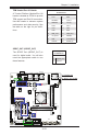
A. Clear CMOS
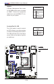
B. Manufacturer
Mode Select
A
B
CMOS Clear
JBT1 is used to clear CMOS. Instead of pins, this "jumper" consists of contact pads
to prevent accidental clearing of CMOS. To clear CMOS, use a metal object such
as a small screwdriver to touch both pads at the same time to short the connec-
tion. Always remove the AC power cord from the system before clearing CMOS.
Note 1: For an ATX power supply, you must completely shut down the
system, remove the AC power cord, and then short JBT1 to clear CMOS.
Note 2: Be sure to remove the onboard CMOS Battery before you short
JBT1 to clear CMOS.
Note 3: Clearing CMOS will also clear all passwords.
Manufacture Mode Select
Close pins 2 and 3 of Jumper JPME2 to
bypass SPI ash security and force the
system to operate in the Manufacture
Mode, allowing the user to flash the
system rmware from a host server for
system setting modications. See the
table on the right for jumper settings.
Manufacture Mode Select
Jumper Settings
Jumper Setting Denition
1-2 Normal (Default)
2-3 Manufacture Mode