
User`s manual


2-24
X10SBA/X10SBA-L User’s Manual
X10SBA(-L)
Rev.
1.01A
JSMB1
J31
JBT1
BT2
M-SATA0M-SATA1
M-SATA2
M-SATA3
JP1
LAN1LAN2
JDIMM2
PJ1
JF1
JTPM1
JOH1
JSPDIF_OUT
JPUSB1
JPAC1
JPME2
JD1
VGA
FAN1
FAN2
I-SATA1
COM4
COM2
SP1
JSD1
JDIMM1
LED3
LED4
LED2
JPW1
SMBUS1
SLOT1 PCI-E 2.0 X2 (IN X8)
USB4/5
USB6
AUDIO FP
SODIMM2 (1.35V only)
USB1(2.0)
USB0(3.0)
CPU
(Install first)SODIMM1(1.35V only)
eDP
Non-ECC DDR3 Required
HDMI/DP
COM3
FP CTRL
BIOS
BAR CODE
J1
(for mini-PCI-E only)
(for M-SATA only)
J2
COM1
(for X10SBA only)
(for X10SBA only)
(for X10SBA only)
(for X10SBA)
LED1
LED5
USB2/3
I-SATA0
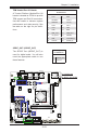
A. JSMB1
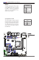
B. Overheat/Fan Fail
LED
A
SMBUS1
A System Management Bus header
for the SMBus slave sensor is located
at JSMB1. Connect the appropriate
cable here to use the SMBus I
2
C con-
nection on your system.
SMBUS1 Header
Pin Denitions
Pin# Denition
1 Data
2 Ground
3 Clock
4 No Connection
Overheat/Fan Fail LED
The JOH1 header is used to connect
an LED indicator to provide warnings
of chassis overheating and fan failure.
This LED will blink when a fan failure
occurs. Refer to the table on right for
pin denitions.
OH/Fan Fail LED
Status
State Message
Solid Overheat
Blinking Fan Fail
B