
User`s manual


Chapter 2: Installation
2-21
X10SBA(-L)
Rev.
1.01A
JSMB1
J31
JBT1
BT2
M-SATA0M-SATA1
M-SATA2
M-SATA3
JP1
LAN1LAN2
JDIMM2
PJ1
JF1
JTPM1
JOH1
JSPDIF_OUT
JPUSB1
JPAC1
JPME2
JD1
VGA
FAN1
FAN2
I-SATA1
COM4
COM2
SP1
JSD1
JDIMM1
LED3
LED4
LED2
JPW1
SMBUS1
SLOT1 PCI-E 2.0 X2 (IN X8)
USB4/5
USB6
AUDIO FP
SODIMM2 (1.35V only)
USB1(2.0)
USB0(3.0)
CPU
(Install first)SODIMM1(1.35V only)
eDP
Non-ECC DDR3 Required
HDMI/DP
COM3
FP CTRL
BIOS
BAR CODE
J1
(for mini-PCI-E only)
(for M-SATA only)
J2
COM1
(for X10SBA only)
(for X10SBA only)
(for X10SBA only)
(for X10SBA)
LED1
LED5
USB2/3
I-SATA0
A
B
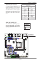
Internal Buzzer (SP1)
The Internal Buzzer (SP1) can be
used to provide audible indications for
various beep codes. See the tables on
the right for pin denitions.
A. Internal Buzzer
B. PWR LED/Speaker
Header
Internal Buzzer
Pin Denition
Pin# Denitions
Pin 1 Pos. (+) Beep In
Pin 2 Neg. (-) Alarm
Speaker
Speaker Connector
Pin Denitions
Pin Setting Denition
Pins 3-4 Internal Speaker
Pins 1-4 External Speaker
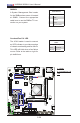
Power LED/Speaker
Pins 1-3 of JD1 are used for power
LED indication, and pins 4-7 are for
the speaker. See the tables on the
right for pin denitions. Please note
that the speaker connector pins (4-7)
are used with an external speaker. If
you wish to use the onboard speaker,
you should close pins 6-7 with a cap.
Speaker Connector
Pin Settings
Pin Setting Denition
Pins 4-7 External Speaker
Pins 6-7 Internal Speaker
PWR LED Connector
Pin Denitions
Pin Setting Denition
Pin 1 Anode (+)
Pin2 Cathode (-)
Pin3 NA