
User`s manual


Chapter 2: Installation
2-17
X10SBA(-L)
Rev.
1.01A
JSMB1
J31
JBT1
BT2
M-SATA0M-SATA 1
M-SATA2
M-SATA3
JP1
LAN1LAN2
JDIMM2
PJ1
JF1
JTPM1
JOH1
JSPDIF_OUT
JPUSB1
JPAC1
JPME2
JD1
VGA
FAN1
FAN2
I-SATA1
COM4
COM2
SP1
JSD1
JDIMM1
LED3
LED4
LED2
JPW1
SMBUS1
SLOT1 PCI-E 2.0 X2 (IN X8)
USB4/5
USB6
AUDIO FP
SODIMM2 (1.35V only)
USB1(2.0)
USB0(3.0)
CPU
(Install first)SODIMM1(1.35V only)
eDP
Non-ECC DDR3 Required
HDMI/DP
COM3
FP CTRL
BIOS
BAR CODE
J1
(for mini-PCI-E only)
(for M-SATA only)
J2
COM1
(for X10SBA only)
(for X10SBA only)
(for X10SBA only)
(for X10SBA)
LED1
LED5
USB2/3
I-SATA0
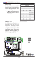
NIC1/NIC2 (LAN1/LAN2)
The NIC (Network Interface Controller)
LED connection for LAN port 1 is located
on pins 11 and 12 of JF1, and the LED
connection for LAN Port 2 is on pins 9 and
10. Attach NIC LED cables to NIC1 and
NIC2 LED indicators to display network
activities. Refer to the table on the right
for pin denitions.
LAN1/LAN2 LED
Pin Denitions (JF1)
Pin# Denition
9/11 Vcc
10/12 Ground
C
A. NIC1 LED
B. NIC2 LED
C. OH/Fan Fail/PWR Fail
Overheat (OH)/Fan Fail
Connect an LED cable to OH/Fan Fail
connections on pins 7 and 8 of JF1 to
provide warnings for overheat, fan failure
or power failure. Refer to the table on the
right for pin denitions.
OH/Fan Fail LED
Pin Denitions (JF1)
Pin# Denition
7 Vcc/Blue UID LED
8 OH/Fan Fail LED
OH/Fan Fail Indicator
Status
State Denition
Off Normal
On Overheat
Flash-
ing
Fan Fail
A
B