
User`s manual


Chapter 2: Installation
2-15
X10SBA(-L)
Rev.
1.01A
JSMB1
J31
JBT1
BT2
M-SATA0M-SATA1
M-SATA2
M-SATA3
JP1
LAN1LAN2
JDIMM2
PJ1
JF1
JTPM1
JOH1
JSPDIF_OUT
JPUSB1
JPAC1
JPME2
JD1
VGA
FAN1
FAN2
I-SATA1
COM4
COM2
SP1
JSD1
JDIMM1
LED3
LED4
LED2
JPW1
SMBUS1
SLOT1 PCI-E 2.0 X2 (IN X8)
USB4/5
USB6
AUDIO FP
SODIMM2 (1.35V only)
USB1(2.0)
USB0(3.0)
CPU
(Install first)SODIMM1(1.35V only)
eDP
Non-ECC DDR3 Required
HDMI/DP
COM3
FP CTRL
BIOS
BAR CODE
J1
(for mini-PCI-E only)
(for M-SATA only)
J2
COM1
(for X10SBA only)
(for X10SBA only)
(for X10SBA only)
(for X10SBA)
LED1
LED5
USB2/3
I-SATA0
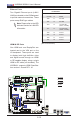
Front Control Panel
JF1 contains header pins for various buttons and indicators that are normally located
on a control panel at the front of the chassis. These connectors are designed spe-
cically for use with Supermicro chassis. See the gure below for the descriptions
of the front control panel buttons and LED indicators. Refer to the following section
for descriptions and pin denitions.
JF1 Header Pins