
User`s manual


2-12
X10SBA/X10SBA-L User’s Manual
Ethernet Ports
Two Gigabit Ethernet ports (LAN1/
LAN2) are located on the I/O Backpanel
to provide network connections. These
ports accept RJ45 type cables.
Note: Please refer to the LED
Indicator Section for LAN LED
information.
LAN Ports
Pin Denition
Pin# Denition
1 P2V5SB 10 SGND
2 TD0+ 11 Act LED
3 TD0- 12 P3V3SB
4 TD1+ 13 Link 100 LED
(Green, +3V3SB)
5 TD1- 14 Link 1000 LED
(Yellow, +3V3SB)
6 TD2+ 15 Ground
7 TD2- 16 Ground
8 TD3+ 17 Ground
9 TD3- 88 Ground
(NC: No Connection)
A. LAN1
B. LAN2
C. HDMI
D. DP
HDMI & DP Ports
One HDMI and one DisplayPort are
located next to the VGA port on the
I/O backpanel. These ports are used
to display both high denition video
and digital sound through an HDMI
or DP-capable display, using a single
HDMI or DP cable (not included). The
X10SBA/-L supports HDMI Specica-
tion version 1.4a and DP 1.1a.
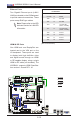
X10SBA(-L)
Rev.
1.01A
JSMB1
J31
JBT1
BT2
M-SATA0M-SATA1
M-SATA2
M-SATA3
JP1
LAN1LAN2
JDIMM2
PJ1
JF1
JTPM1
JOH1
JSPDIF_OUT
JPUSB1
JPAC1
JPME2
JD1
VGA
FAN1
FAN2
I-SATA1
COM4
COM2
SP1
JSD1
JDIMM1
LED3
LED4
LED2
JPW1
SMBUS1
SLOT1 PCI-E 2.0 X2 (IN X8)
USB4/5
USB6
AUDIO FP
SODIMM2 (1.35V only)
USB1(2.0)
USB0(3.0)
CPU
(Install first)SODIMM1(1.35V only)
eDP
Non-ECC DDR3 Required
HDMI/DP
COM3
FP CTRL
BIOS
BAR CODE
J1
(for mini-PCI-E only)
(for M-SATA only)
J2
COM1
(for X10SBA only)
(for X10SBA only)
(for X10SBA only)
(for X10SBA)
LED1
LED5
USB2/3
I-SATA0
A
B
C
D