
User`s manual


Chapter 1: Introduction
1-5
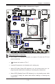
X10SBA/X10SBA-L Jumpers
Jumper Description Default
JBT1 CMOS Clear Open: Normal (See Chpt. 2)
JPAC1 Audio Enable Pins 1-2 (Enabled)
JPME2 Intel Manufacturer Mode Select Pins 1-2 (Normal)
JPUSB1 USB Wake-Up Enable Pins 1-2 (Enabled)
X10SBA/X10SBA-L Headers/Connectors
Connector Description
Audio FP Front Panel Audio Header
Battery Onboard Battery (BT2)
COM1-COM4 COM1/COM2/COM3/COM4 Headers
eDP Embedded DisplayPort (J5) (Only available on the X10SBA)
Fan1/Fan2 System/CPU Fan Headers
HDMI/DP (Backpanel) HDMI/DisplayPort
J1 mini-PCI-E Slot for a mini-PCI-E Card (Only available on the
X10SBA)
J2 mSATA Slot MUX with I-SATA-1 (Only available on the X10SBA)
Note: mSATA MUX (J2) support is available only when I-SATA1 is
not in use. J2 and I-SATA1 cannot be used together.
J4 (Slot 1) PCI-E 2.0 x 2 in x8 Slot
JD1 Power LED/Speaker Header (Pins 1-3: Power LED, Pins 6-7: Internal
Buzzer, Pins 4-7: External Speaker)
JF1 Front Panel Control Header
JOH1 Overheat LED Indicator Header
JPW1 24-pin ATX Main Power Connector (Optional Power Source)
JSD1 SATA DOM (Device_On_Module) Power Connector
JSPDIF_OUT S/PDIF (Sony/Phillips Digital Interconnect Format) Audio Output
Header
JTPM1 Trusted Platform Module/Port 80 Connector
LAN1/LAN2 Gigabit Ethernet (RJ45) Ports (LAN1/2)
PJ1 4-pin 12V Power Connector (Optional Power Source)
(I-)SATA0/1 (Intel-)Serial ATA (SATA 2.0) Ports 0/1 (Optional Power Source)
Note: J2 and I-SATA1 cannot be used together.
(M-)SATA0-3 Marvell 88SE9230 Serial ATA (SATA 3.0) Ports 0-3 (Only available
on the X10SBA)
SMBUS1 (JSMB1) 4-Pin External System Management Bus I
2
C Header (JSMB1)