
User`s manual


Chapter 1: Introduction
1-3
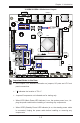
X10SBA/X10SBA-L Motherboard Layout
Important Notes to the User
•See Chapter 2 for detailed information on jumpers, I/O ports and JF1 front
panel connections.
•" " indicates the location of "Pin 1".
•Jumpers/Components not indicated are for testing only.
•When LED1 (Main Power LED Indicator) is on, the system power is on, Un-
plug the power cable before installing or removing any components.
•When LED5 (Standby Power LED Indicator) is on, the standby power cable
is connected, Unplug the power cable before installing or removing any
components.
X10SBA(-L)
Rev.
1.01A
JSMB1
J31
JBT1
BT2
M-SATA0M-SATA1
M-SATA2
M-SATA3
JP1
LAN1LAN2
JDIMM2
PJ1
JF1
JTPM1
JOH1
JSPDIF_OUT
JPUSB1
JPAC1
JPME2
JD1
VGA
FAN1
FAN2
I-SATA1
COM4
COM2
SP1
JSD1
JDIMM1
LED3
LED4
LED2
JPW1
SMBUS1
SLOT1 PCI-E 2.0 X2 (IN X8)
USB4/5
USB6
AUDIO FP
SODIMM2 (1.35V only)
USB1(2.0)
USB0(3.0)
CPU
(Install first)SODIMM1(1.35V only)
eDP
Non-ECC DDR3 Required
HDMI/DP
COM3
FP CTRL
BIOS
BAR CODE
J1
(for mini-PCI-E only)
(for M-SATA only)
J2
COM1
(for X10SBA only)
(for X10SBA only)
(for X10SBA only)
(for X10SBA)
LED1
LED5
USB2/3
I-SATA0