
User`s manual


Chapter 2: Installation
2-25
S
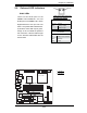
UPER PDSML-LN1+/LN2+/E+
®
LGA 775 CPU
KB/MS
JLAN1
Intel
3000/3010
North Bridge
4
naF
24-Pin
ATX
PW
R
ICH7R
South Bridge
8-pin PWR
Battery
USB 1/2
VGA
JLAN2
COM2
Floppy
DIMM 2B
PCI-E x8
BIOS
IDE
JPF
DIMM 1B
DIMM 2A
DIMM 1A
Fan1
J 8
Fan5
LAN
CTRL2
JPL2
JPL1
WOL
JWOR
rezzuB
JL 1
JI
2
C1
JBT1
SATA1
JPG1
Fan3
FP CTRL
JF
1
Fan2
USB3/4
LAN
CTRL1
SPKR
JI
2
C2
IPMI
Slot6
SBX: PCI-33 MHz
VGA
CTRL
J1 0
PCI-E x4
Slot5
PCI1
Slot4
PCI-33 MHz
LE3
COM1
VGA
Memory
LE4
LE
1
JL
E
D
Fan6
CPU
Fan
JPR1
PWR FaultPWR SMB
(*LN2+)
(*LN2+)
USB5/6
SATA0 SATA2
SATA3
S I/O
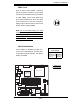
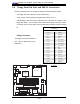
GLAN LEDs
There are two GLAN ports on the
PDSML-LN2+/PDSML-E+ and one
GLAN port on the PDSML-LN1+. Each
Gigabit Ethernet LAN port has two
LEDs. The yellow LED indicates activ-
ity while the other LED may be green,
orange or off to indicate the speed of
the connection. See the table at right
for the functions associated with the
second LED.
2-8 Onboard LED Indicators
Link
Activity
GLAN LED
Link Indicator
LED Color Defi nition
Off 10Mbps or No Connection
Green 100 Mbps
Amber 1 Gbps
GLAN Activity LED Indicator
LED Color Defi nition
Yellow Flashing: 10Mbps/
100Mbps/1 Gbps
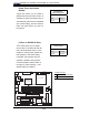
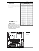
A. GLAN 1
B. GLAN 2
A
B
(*Rear View: When facing the
rear side of the system)