
User`s manual


2-24
PDSML-LN1+/PDSML-LN2+/PDSML-E+ User's Manual
S
UPER PDSML-LN1+/LN2+/E+
®
LGA 775 CPU
KB/MS
JLAN1
Intel
3000/3010
North Bridge
4
na
F
24-Pin ATX
PW
R
ICH7R
South Bridge
8-pin PWR
Battery
USB 1/2
VGA
JLAN2
COM2
Floppy
DIMM 2B
PCI-E x8
BIOS
IDE
JPF
DIMM 1B
DIMM 2A
DIMM 1A
Fan1
J 8
Fan5
LAN
CTRL2
JPL2
JPL1
WOL
JWOR
rezzuB
JL 1
JI
2
C1
JBT1
SATA1
JPG1
Fan3
FP CTRL
JF
1
Fan2
USB3/4
LAN
CTRL1
SPKR
JI
2
C2
IPMI
Slot6
SBX: PCI-33 MHz
VGA
CTRL
J1 0
PCI-E x4
Slot5
PCI1
Slot4
PCI-33 MHz
LE3
COM1
VGA
Memory
LE4
LE1
JL
E
D
Fan6
CPU
Fan
JPR1
PWR FaultPWR SMB
(*LN2+)
(*LN2+)
USB5/6
SATA0 SATA2
SATA3
S I/O
Power Force On Enable/
Disable
Jumper JPF allows you to enable or
disable the Power Force On function. If
enabled, the power will always stay on
automatically. If this function is disabled
(the normal setting), the user needs to
press the power button to power on
the system.
Power Force On
Enable/Disable
Jumper Settings (JPF)
Jumper Setting Defi nition
Open Normal
Closed Force On
I
2
C Bus to PCI/PCI-E Slots
JI
2
C1/JI
2
C2 allows you to enable
the I
2
C Bus to communicate with all
PCI and PCI-Express slots. For the
jumpers to work properly, please set
both jumpers to the same setting.
If enabled, both jumpers must be
enabled. If disabled, both jumpers
must be disabled. See the table on
the right for jumper settings. (The
default setting is enabled.)
I
2
C Bus to PCI Slots 1/2
Jumper Settings
Jumper Setting Defi nition
Open Disabled
Closed Enabled
A. PWR Force On
B. I
2
C Bus to PCI/PCI-E Slots
C. I
2
C Bus to PCI/PCI-E Slots
A
B
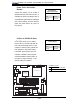
C