
User`s manual
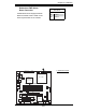


Chapter 2: Installation
2-23
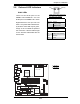
S
UPE
R PDSML-LN1+/LN2+/E+
®
LGA 775 CPU
KB/MS
JLAN1
Intel
3000/3010
North Bridge
4
n
aF
24-Pin ATX
PW
R
ICH7R
South Bridge
8-pin PWR
Battery
USB 1/2
VGA
JLAN2
COM2
Floppy
DIMM 2B
PCI-E x8
BIOS
IDE
JPF
DIMM 1B
DIMM 2A
DIMM 1A
Fan1
J 8
Fan5
LAN
CTRL2
JPL2
JPL1
WO
L
JWOR
rezzuB
JL 1
JI
2
C1
JBT1
SATA1
JPG1
Fan3
FP CTRL
JF
1
Fan2
USB3/4
LAN
CTRL1
SPKR
JI
2
C2
IPMI
Slot6
SBX: PCI-33 MHz
VGA
CTRL
J1 0
PCI-E x4
Slot5
PCI1
Slot4
PCI-33 MHz
LE3
COM1
VGA
Memory
LE4
LE
1
JL
E
D
Fan6
CPU
Fan
JPR1
PWR FaultPWR SMB
(*LN2+)
(*LN2+)
USB5/6
SATA0 SATA2
SATA3
S I/O
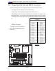
CMOS Clear
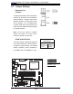
JBT1 is used to clear CMOS. Instead of
pins, this "jumper" consists of contact pads
to prevent the accidental clearing of CMOS.
To clear CMOS, use a metal object such
as a small screwdriver to touch both pads
at the same time to short the connection.
Always remove the AC power cord from the
system before clearing CMOS.
Note: For an ATX power supply, you must
completely shut down the system, remove
the AC power cord and then short JBT1
to clear CMOS. Do not use the PW_ON
connector to clear CMOS.
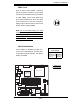
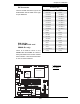
VGA Enable/Disable
JPG1 enables or disables the VGA Con-
nector on the motherboard. See the table
on the right for jumper settings. The default
setting is enabled.
VGA Enable/Disable
Jumper Settings
Jumper Setting Defi nition
Pins 1-2 Enabled
Pins 2-3 Disabled
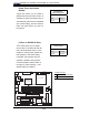
A. CMOS Clear
B. VGA Enable
A
B