
User`s manual


2-22
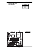
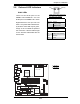
PDSML-LN1+/PDSML-LN2+/PDSML-E+ User's Manual
S
UPE
R PDSML-LN1+/LN2+/E+
®
LGA 775 CPU
KB/MS
JLAN1
Intel
3000/3010
North Bridge
4
na
F
24-Pin ATX PWR
ICH7R
South Bridge
8-pin PWR
Battery
USB 1/2
VGA
JLAN2
COM2
Floppy
DIMM 2B
PCI-E x8
BIOS
IDE
JPF
DIMM 1B
DIMM 2A
DIMM 1A
Fan1
J 8
Fan5
LAN
CTRL2
JPL2
JPL1
WOL
JWOR
rezzuB
JL 1
JI
2
C1
JBT1
SATA1
JPG1
Fan3
FP CTRL
JF
1
Fan2
USB3/4
LAN
CTRL1
SPKR
JI
2
C2
IPMI
Slot6
SBX: PCI-33 MHz
VGA
CTRL
J1 0
PCI-E x4
Slot5
PCI1
Slot4
PCI-33 MHz
LE3
COM1
VGA
Memory
LE4
LE
1
JL
E
D
Fan6
CPU
Fan
JPR1
PWR FaultPWR SMB
(*LN2+)
(*LN2+)
USB5/6
SATA0 SATA2
SATA3
S I/O
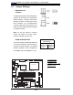
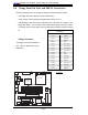
2-7 Jumper Settings
Explanation of
Jumpers
To modify the operation of the motherboard,
jumpers can be used to choose between
optional settings. Jumpers create shorts
between two pins to change the function
of the connector. Pin 1 is identifi ed with
a square solder pad on the printed circuit
board. See the motherboard layout pages
for jumper locations.
Note: On two pin jumpers, "Closed"
means the jumper is on and "Open"
means the jumper is off the pins.
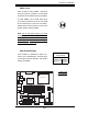
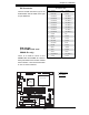
GLAN Enable/Disable
JPL1/JPL2 enable or disable GLAN Ports
1/2 on the motherboard. See the table on
the right for jumper settings. The default
setting is enabled. (*JPL2 is available on
the PDSML-LN2+ and PDSML-E+ only.)
GLAN Enable
Jumper Settings
Jumper Setting Defi nition
Pins 1-2 Enabled
Pins 2-3 Disabled
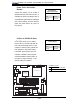
A. GLAN1 Enable
B. GLAN2 Enable
( * P D S M L - L N 2 + a n d
PDSML-E+ only)
A
B