
User`s manual


Chapter 2: Installation
2-19
S
UPER
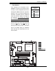
PDSML-LN1+/LN2+/E
+
®
LGA 775 CPU
KB/MS
JLAN1
Intel
3000/3010
North Bridge
4naF
24-Pin ATX PWR
ICH7R
South Bridge
8-pin PWR
Battery
USB 1/2
VGA
JLAN2
COM2
Floppy
DIMM 2B
PCI-E x8
BIOS
IDE
J
PF
DIMM 1B
DIMM 2A
DIMM 1A
Fan1
J 8
Fan5
LAN
CTRL2
JPL2
JPL1
WO
L
JWOR
r
e
z
zuB
JL 1
JI
2
C1
JBT1
SATA1
JPG1
Fan3
FP CTRL
JF1
Fan2
USB3/4
LAN
CTRL1
SPKR
JI
2
C2
IPMI
Slot6
SBX: PCI-33 MHz
VGA
CTRL
J1 0
PCI-E x4
Slot5
PCI1
Slot4
PCI-33 MHz
LE
3
COM1
VGA
Memory
LE4
LE1
J
L
ED
Fan6
CPU
Fan
JPR1
PWR FaultPWR SMB
(*LN2+)
(*LN2+)
USB5/6
SATA0 SATA2
SATA3
S I/O
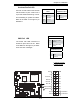
Power LED
The Power LED connector is desig-
nated JLED. This connection is used
for 3-pin LED applications. It is used
to indicate that power has been sup-
plied to the system. See the table on
the right for pin defi nitions. For 2-pin
power LED, please see Power LED
on page 2-9.
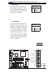
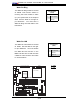
VGA Connector
A VGA connector (JG1) is located next
to the COM1 port on the IO backplane.
Refer to the board layout below for
the location.
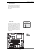
PWR LED
Pin Defi nitions
Pin# Defi nition
1 +5V
2 Key
3 Ground
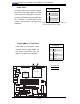
A. VGA
B. PWR LED
A
B