
User`s manual


Chapter 2: Installation
2-17
S
UPER
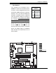
PDSML-LN1+/LN2
+/E+
®
LGA 775 CPU
KB/MS
JLAN1
Intel
3000/3010
North Bridge
4
n
aF
24-Pin ATX
PWR
ICH7R
South Bridge
8-pin PWR
Battery
USB 1/2
VGA
JLAN2
COM2
Floppy
DIMM 2B
PCI-E x8
BIOS
IDE
J
P
F
DIMM 1B
DIMM 2A
DIMM 1A
Fan1
J 8
Fan5
LAN
CTRL2
JPL2
JPL1
WO
L
JWOR
r
e
z
z
uB
JL1
JI
2
C1
JBT1
SATA1
JPG1
Fan3
FP CTRL
JF
1
Fan2
USB3/4
LAN
CTRL1
SPKR
JI
2
C2
IPMI
Slot6
SBX: PCI-33 MHz
VGA
CTRL
J10
PCI-E x4
Slot5
PCI1
Slot4
PCI-33 MHz
LE 3
COM1
VGA
Memory
LE
4
LE 1
J
LED
Fan6
CPU
Fan
JPR1
PWR FaultPWR SMB
(*LN2+)
(*LN2+)
USB5/6
SATA0 SATA2
SATA3
S I/O
Fan Header
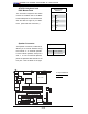
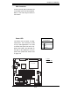
Pin Defi nitions
(Fan1-5)
Pin# Defi nition
1 Ground (Black)
2 +12V (Red)
3 Tachometer
4 PWM_Control
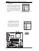
Fan Headers
T h e P D S M L - L N 1 + / P D S M L - L N 2 + /
PDSML-E+ has six fan connections (Fan1
to Fan6). Fan6 is designated as the CPU
Cooling Fan. Note: all fans are 4-pin fans.
However, Pins 1-3 of the fan headers are
backward compatible with the traditional
3-pin fans. See the table on the right for
pin defi nitions. The onboard fan speeds
are controlled by Thermal Management
in the BIOS Hardware Monitoring Setting.
When using Thermal Management setting,
please use all 3-pin fans or all 4-pin fans
on the motherboard. Please do not use
both 3-pin fans and 4-pin fans on the same
board. The default setting is "Disabled"
which will allow the onboard fans to run at
the full speed.
A. Fan1
B. Fan2
C. Fan3
D. Fan4
E. Fan5
F. Fan6 (CPU Fan)
A
B
C
D
E
DF