
User`s manual


Chapter 2: Installation
2-15
S
UPER
PDSML-LN1+/LN2+/E+
®
LGA 775 CPU
KB/MS
JLAN1
Intel
3000/3010
North Bridge
4na
F
24-Pin
ATX PW
R
ICH7R
South Bridge
8-pin PWR
Battery
USB 1/2
VGA
JLAN2
COM2
Floppy
DIMM 2B
PCI-E x8
BIOS
IDE
J
PF
DIMM 1B
DIMM 2A
DIMM 1A
Fan1
J 8
Fan5
LAN
CTRL2
JPL2
JPL1
WO
L
JWOR
re
z
zu
B
JL 1
JI
2
C1
JBT1
SATA1
JPG1
Fan3
FP CTRL
JF
1
Fan2
USB3/4
LAN
CTRL1
SPKR
JI
2
C2
IPMI
Slot6
SBX: PCI-33 MHz
VGA
CTRL
J1 0
PCI-E x4
Slot5
PCI1
Slot4
PCI-33 MHz
LE
3
COM1
VGA
Memory
LE4
LE1
J
L
ED
Fan6
CPU
Fan
JPR1
PWR FaultPWR SMB
(*LN2+)
(*LN2+)
USB5/6
SATA0 SATA2
SATA3
S I/O
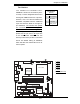
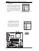
A. BP USB 1/2
B. FP USB 3/4
C. FP USB 5/6
D. GLAN1
E. GLAN2 (*PDSML-LN2+
and PDSML-E+ only.)
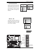
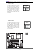
Universal Serial Bus (USB)
There are two Universal Serial Bus
ports (BP USB 1/2) (J15) located on
the I/O back panel and additional four
USB ports located at J46 (FP USB
3/4) and J45 (FP USB 5/6) on the
motherboard. These ports (FP USB3
/4, FPUSB 5/6) can be used to pro-
vide front side chassis access. Note:
cables are not included. See the table
on the right for pin defi nitions.
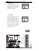
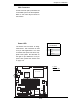
GLAN (Giga-bit Ethernet
Ports)
There is a Giga-bit (GLAN) Ethernet
port on the PDSML-LN1+ and two
GLAN ports on the PDSML-LN2+
and PDSML-E+. The GLAN ports are
located next to the VGA port on the IO
backplane. The GLAN port accepts
RJ45 type cables.
Universal Serial Bus
Pin Defi nitions
Back Panel USB
Pin # Defi nition
Front Panel USB
Pin # Defi nition
1 +5V 1 +5V
2 PO- 2 PO-
3 PO+ 3 PO+
4 Ground 4 Ground
5 N/A 5 Key
A
B
C
D
E