
User`s manual


Chapter 2: Installation
2-13
S
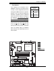
UPER PDSML-LN1+/LN2+/E+
®
LGA 775 CPU
KB/MS
JLAN1
Intel
3000/3010
North Bridge
4
naF
24-Pin
ATX
PW
R
ICH7R
South Bridge
8-pin PWR
Battery
USB 1/2
VGA
JLAN2
COM2
Floppy
DIMM 2B
PCI-E x8
BIOS
IDE
JPF
DIMM 1B
DIMM 2A
DIMM 1A
Fan1
J 8
Fan5
LAN
CTRL2
JPL2
JPL1
WOL
JWOR
rezzuB
JL 1
JI
2
C1
JBT1
SATA1
JPG1
Fan3
FP CTRL
JF
1
Fan2
USB3/4
LAN
CTRL1
SPKR
JI
2
C2
IPMI
Slot6
SBX: PCI-33 MHz
VGA
CTRL
J1 0
PCI-E x4
Slot5
PCI1
Slot4
PCI-33 MHz
LE3
COM1
VGA
Memory
LE4
LE
1
JL
E
D
Fan6
CPU
Fan
JPR1
PWR FaultPWR SMB
(*LN2+)
(*LN2+)
USB5/6
SATA0 SATA2
SATA3
S I/O
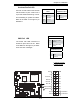
2-6 Connectors and Headers
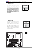
ATX Power Connector
The main power supply connec-
tor (JPW1) on the PDSML-LN1+/
PDSML-LN2+/PDSML-E+ meets the
Server System Infrastructure (SSI)
specification. You can only use a
24-pin power supply cable on the
motherboard. Make sure that the
orientation of the connector is cor-
rect. You must also use the 8-pin
(JPW2) processor power connector
for adequate power supply to the
system (See below). See the table
on the right for pin defi nitions.
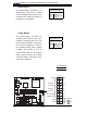
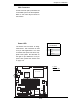
Processor Power Connector
In addition to the Primary ATX power
connector (above), the 12V 8-pin Pro-
cessor connector at JPW2 must also
be connected to your power supply
to provide adequate power supply to
the system.
8-pin Processor Power
Pin Defi nitions
Pins Defi nition
1 through 4 Ground
5 through 8 +12V
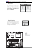
ATX Power 24-pin Connector
Pin Defi nitions
Pin# Defi nition Pin # Defi nition
13 +3.3V 1 +3.3V
14 -12V 2 +3.3V
15 COM 3 COM
16 PS_ON 4 +5V
17 COM 5 COM
18 COM 6 +5V
19 COM 7 COM
20 Res (NC) 8 PWR_OK
21 +5V 9 5VSB
22 +5V 10 +12V
23 +5V 11 +12V
24 COM 12 +3.3V
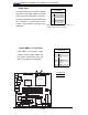
A. 24-pin ATX PWR
B. 8-pin Processor PWR
A
B