
User`s manual

2-8
PDSML-LN1+/PDSML-LN2+/PDSML-E+ User's Manual
S
UPER
PDSML-LN1+/LN2
+/E+
®
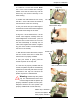
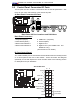
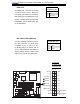
B. Front Control Panel
JF1 contains header pins for various buttons and indicators that are normally located
on a control panel at the front of the chassis. These connectors are designed
specifi cally for use with Supermicro server chassis. Refer to the following section
for descriptions and pin defi nitions.
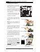
JF1 Header Pins
Power Button
OH/Fan Fail LED
1
NIC1 LED
Reset Button
2
HDD LED
Power LED
Reset
PWR
Vcc
Vcc
Vcc
Vcc
Ground
Ground
1920
Vcc
X
Ground
NMI
X
Vcc
PWR Fail LED
NIC2 LED
S
UPER PDSML-LN1+/LN2+/E+
®
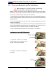
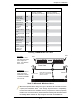
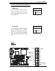
2-5 Control Panel Connectors/IO Ports
The I/O ports are color coded in conformance with the PC 99 specifi cation. See
below for the colors and locations of the various I/O ports.
A. Back Panel Connectors/IO Ports
Back Panel I/O Port Locations and Defi nitions
Back Panel Connectors
1. Keyboard (Purple) 5. COM Port 1 (Turquoise)
2. PS/2 Mouse (Green) 6. VGA Port (Blue)
3. Back Panel USB Port 1 7. Gigabit LAN 1
4. Back Panel USB Port 2. 8. Gigabit LAN 2 (*For PDSML-LN2+ and
PDSML-E+ only.)
(*See Section 2-6 for details.)
1
2
3
4
5
6
7
8