
User`s manual

Chapter 2: Installation
2-7
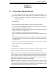
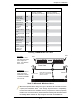
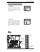
To Install:
Insert module verti-
cally and press down
until it snaps into
place. Pay attention
to the notch.
Installing a DIMM Module into a Slot
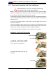
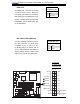
To Remove:
Use your thumbs to
gently push each
release tab outward
to release the DIMM
from the slot.
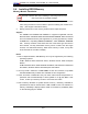
Possible System Memory Allocation & Availability
System Device Size Physical Memory
Remaining (-Available)
(3 GB Total System Memory)
Physical Memory
Remaining (-Available)
(4 GB Total System Memory)
Firmware Hub
fl ash memory
(System BIOS)
1 MB 3.00 3.99
Local APIC 4 KB 3.00 3.99
Area Reserved
for the chipset
2 MB 3.00 3.99
I/O APIC (4
Kbytes)
4 KB 3.00 3.99
PCI Enumeration
Area 1
256 MB 3.00 3.76
PCI Express (256
MB)
256 MB 3.00 3.51
PCI Enumeration
Area 2 (if needed)
-Aligned on 256-
MB boundary-
512 MB 3.00 3.01
VGA Memory 16 MB 2.85 2.85
TSEG 1 MB 2.84 2.84
Memory available
to BIOS, OS,
applications
2.84 2.84
Microsoft implemented a design change in Windows XP with Service Pack
2 (SP2) and Windows Vista. This change improves driver compatibility,
but however reduces the available memory compared to what is physically
insalled. For more information, please read the following article at Microsoft's
Knowledge Base website at: http://support.microsoft.com/kb/888137.
Note To Microsoft Windows Users
Release Tab
Release Tab
Note: Notch should align
with the receptive key
point on the slot.
Notch
Notch
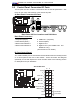
Front View