
User`s manual

1-4
PDSML-LN1+/PDSML-LN2+/PDSML-E+ User’s Manual
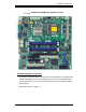
Important Notes to the User
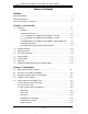
• Note 1 All images and graphics shown in this manual were based upon the
latest PCB Revision available at the time of publishing of this manual. The
motherboard you've received may or may not look exactly the same as the
graphics shown in this manual.
• Note 2 See Chapter 2 for detailed information on jumpers, I/O ports and JF1
front panel connections.
• Note 3 " " indicates the location of Pin 1.
• Note 4 When the LE1 LED is on, onboard power is on. Maker sure to unplug
the AC power cord before installing or removing components.
• Note 5 IPMI and LAN2 are available on the PDSML-LN2+ and PDSML-E+
only. To use IPMI, install the optional AOC-SIM1U/SIM1U+ or AOC-SIMLC
IPMI card on the IPMI slot (J19). Please refer to page 1-13 for more informa-
tion.
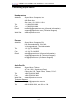
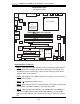
Motherboard Layout
(not drawn to scale)
S
UPER
PDSML-LN1+/LN2+/E+
®
LGA 775 CPU
KB/MS
JLAN1
Intel
3000
North Bridge
4
n
aF
24-Pin ATX PWR
ICH7R
South Bridge
J 2 8
8-pin PWR
Battery
J 9
USB 1/2
J 1 5
VGA
JG1
JLAN2
COM2
Floppy
DIMM 2B
PCI-E x8
BIOS
JPW1
J27
3J
IDE
JPF
DIMM 1B
DIMM 2A
DIMM 1A
DIMM 1
DIMM 2
DIMM 3
DIMM 4
Fan1
JPW2
J 8
Fan5
LAN
CTRL2
JPL2
JPL1
WOL
JWOR
rezz
uB
J45
JL1
JI
2
C1
JBT1
J
4
6
SATA1
JPG1
Fan3
FP CTRL
JF
1
Fan2
USB3/4
LAN
CTRL1
SPKR
JI
2
C2
IPMI
J19
Slot6
SBX: PCI-33 MHz
VGA
CTRL
PCI2
J10
PCI-E x4
Slot5
PCI1
Slot4
PCI-33 MHz
LE3
COM1
J 3 1
VGA
Memory
LE4
LE1
JS 1
JS 2
JS 3
JS 4
JL
E
D
Fan6
CPU
Fan
JPR1
PW3
PWRFault
PW4
PWR SMB
(*LN2+)
(*LN2+)
USB5/6
SATA0
SATA2
SATA3
PDSML-E+ Only
3010
OR
Intel
S I/O