
User`s manual


Chapter 2: Installation
2-21
S
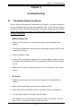
UPER PDSBA+
®
Processor
JP WA KE
4-PinPWR
KB/MS
USB3/4/5/6
USB1/2
LAN
Fan3
Clock
Intel
North Bridge
PCI-E x1
PCI-E x16
PCI-E x4
PCI-33MHz
LAN
CTRL
JPL 1
COM2
FWH
JL1
JWOR
I-SATA0
I-SATA1
FP C TRL
Fan2
Buzzer
24 - P in ATX P W R
Super IO
Fan1/CPU Fan
Intel
J44
DIMM#1 A (Blue)
DIMM#2A (B lack)
DIMM#1 B (Blue)
DIMM#2B (B lack)
Fl opp y
Audio
WOL
JBT1
South Bridge
J12
Battery
JPUSB1
JP U SB 2
COM1
JFSB1
JFSB2
Slot7
Slot6
Slot5
Slot4
JI
2
C1
JI
2
C2
PCI-33MHz
Slot3
PCI-33MHz
Slot2
Slot1
PCI-33MHz
J9
I-SATA4
I-SATA5
RAIDLED
USB7/8
J45
USB9/10
LE1
JLED
JWD
CD1
Parallel Port
VG A
HDA
ID E #2
ID E #1
ITE
JP2
JP3
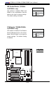
USB Wake-Up
Use JPUSB jumpers to enable the function of
"System Wake-Up via USB devices", which al-
lows you to "wake-up" the system by pressing a
key on the USB keyboard or by clicking the USB
mouse of your system. The JPUSB jumpers are
used together with the USB Wake-Up function
in the BIOS. Enable both the jumpers and the
BIOS setting to allow the system to "wake-up
via USB Devices". See the table on the right for
jumper settings and jumper connections. (Note:
JPUSB1 is for Back Panel USB ports:1~6, and
JPUSB2 is for Front Panel USB ports:7~10.)
(Note: The default jumper setting for the USB
ports is Disabled. However, when the "USB
Wake-Up" function is enabled in the BIOS,
and the desired USB ports are enabled via the
JPUSB jumper, please be sure to remove all
USB devices from the USB ports whose USB
jumpers are set to Disabled before the system
goes into the standby mode.)
JPUSB1 (Back Panel USB
Wake-up)
Pin# Denition
1-2 Enabled
2-3 Disabled (*default)
JPUSB2 (Front Panel USB
Wake-up)
Pin# Denition
1-2 Enabled
2-3 Disabled (*default)
A
B
A. BP USB Wake-up
B. FP USB Wake-up