
User`s manual


2-20
PDSBA-Q+/PDSBA+/PDSBA/PDSBE User's Manual
S
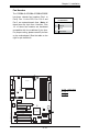
UPER PDSBA+
®
Processor
JP WA KE
4-PinPWR
KB/MS
USB3/4/5/6
USB1/2
LAN
Fan3
Clock
Intel
North Bridge
PCI-E x1
PCI-E x16
PCI-E x4
PCI-33MHz
LAN
CTRL
JPL1
COM2
FWH
JL1
JWOR
I-SATA0
I-SATA1
FP C TRL
Fan2
Buzzer
24 - P i n A TX PWR
Super IO
Fan1/CPU Fan
Intel
J44
DIMM#1 A (Blu e)
DIMM#2A (Black)
DIMM#1 B (Blu e)
DIMM#2B (Black)
Fl opp y
Audio
WOL
JBT1
South Bridge
J12
Battery
JPUSB1
JP US B2
COM1
JFSB1
JFSB2
Slot7
Slot6
Slot5
Slot4
JI
2
C1
JI
2
C2
PCI-33MHz
Slot3
PCI-33MHz
Slot2
Slot1
PCI-33MHz
J9
I-SATA4
I-SATA5
RAIDLED
USB7/8
J45
USB9/10
LE1
JLED
JWD
CD1
Parallel Port
VG A
HDA
ID E# 2
ID E# 1
ITE
JP2
JP3
A
B
A. FSB CPU Speeds
B. PCI slots to SMB
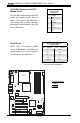
CPU Front Side Bus Speed
JFSB1 and JFSB2 allow you to set the
Front Side Bus Frequency. See the table
on the right for pin denitions. (Default
is Auto.)
CPU FSB Jumper Settings
Jumper Settings
JFSB2 JFSB1 Frequency
1-2 1-2 *Auto
2-3 2-3 266MHz
Open 2-3 200MHz
2-3 Open 133MHz
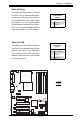
PCI/PCI-E Slots to SMB Speeds
Jumpers JI
2
C1/JI
2
C2 allow you to con-
nect PCI/PCI-Exp. slots to the System
Management Bus. The default setting is
open to disable the connection. See the
table on the right for jumper settings.
SMBus to PCI-X/PCI-Exp Slots
Jumper Settings
Jumper Setting Denition
Closed Enabled
Open Disabled (*Default)