
User`s manual


Chapter 2: Installation
2-19
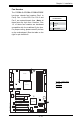
S
UPER PDSBA+
®
Processor
JP WA KE
4-PinPWR
KB/MS
USB3/4/5/6
USB1/2
LAN
Fan3
Clock
Intel
North Bridge
PCI-E x1
PCI-E x16
PCI-E x4
PCI-33MHz
LAN
CTRL
JPL1
COM2
FWH
JL1
JWOR
I-SATA0
I-SATA1
FP C TRL
Fan2
Buzzer
24 - P in ATX PWR
Super IO
Fan1/CPU Fan
Intel
J44
DIMM#1 A (Blue)
DIMM#2A (Black)
DIMM#1 B (Blue)
DIMM#2B (Black)
Fl opp y
Audio
WOL
JBT1
South Bridge
J12
Battery
JPUSB1
JP US B 2
COM1
JFSB1
JFSB2
Slot7
Slot6
Slot5
Slot4
JI
2
C1
JI
2
C2
PCI-33MHz
Slot3
PCI-33MHz
Slot2
Slot1
PCI-33MHz
J9
I-SATA4
I-SATA5
RAIDLED
USB7/8
J45
USB9/10
LE1
JLED
JWD
CD1
Parallel Port
VG A
HDA
ID E #2
ID E #1
ITE
JP2
JP3
CMOS Clear
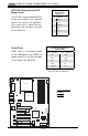
JBT1 is used to clear CMOS. Instead of pins, this "jumper" consists of contact pads
to prevent the accidental clearing of CMOS. To clear CMOS, use a metal object such
as a small screwdriver to touch both pads at the same time to short the connection.
Always remove the AC power cord from the system before clearing CMOS.
Note: For an ATX power supply, you must completely shut down the sys-
tem, remove the AC power cord, and then short JBT1 to clear CMOS.
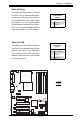
A
B
A. Clear CMOS
B. Watch Dog Enable
Watch Dog Enable/Disable
Watch Dog is a system monitor that can reboot the
system when a software application hangs. Close
Pins 1-2 to reset the system when an application
hangs. Close pins 2-3 to generate a non-maskable
interrupt signal for the application that hangs. See
the table on the right for jumper settings. Watch
Dog must also be enabled in the BIOS.
Note: When enabled, the user needs to
write their own application software in or-
der to disable the Watch Dog Timer.
Watch Dog
Jumper Settings (JWD)
Jumper Setting Denition
Pins 1-2 Reset
(*default)
Pins 2-3 NMI
Open Disabled