
User`s manual


Chapter 2: Installation
2-9
S
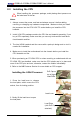
UPER PDSBA+
®
Pr oces sor
JP W A K E
4-PinPWR
KB/MS
USB3/4/5/6
USB1/2
LAN
Fan3
Clock
Intel
North Bridge
PCI-E x1
PCI-E x16
PCI-E x4
PCI-33MHz
LAN
CTRL
JPL 1
COM2
FWH
JL1
JWOR
I-SATA0
I-SATA1
FP CTR L
Fan2
Buzzer
24 - Pi n A TX PWR
Sup er IO
Fan1/CPU Fan
Intel
J44
DIM M# 1A (B lu e)
DIM M# 2A (Bl ack)
DIM M# 1B (B lu e)
DIM M# 2B (Bl ack)
Fl op py
Audi o
WOL
JBT1
South Bridge
J12
Battery
JPUSB1
JP U S B 2
COM1
JFSB1
JFSB2
Slot7
Slot6
Slot5
Slot4
JI
2
C1
JI
2
C2
PCI-33MHz
Slot3
PCI-33MHz
Slot2
Slot1
PCI-33MHz
J9
I-SATA4
I-SATA5
RAIDLED
USB7/8
J45
USB9/10
LE1
JLED
JWD
CD1
Parallel Port
VG A
HDA
ID E # 2
ID E # 1
ITE
JP2
JP3
Power Button
OH/Fan Fail LED
1
NIC1 LED
Reset Button
2
HDD LED
Power LED
Reset
PWR
LED_Anode
LED_Anode
LED_Anode
LED_Anode
Ground
Ground
X
X
X
X
NIC1 Indicator
The NIC (Network Interface Control-
ler) LED connection for GLAN port1
is located on pins 11 and 12 of JF1.
Attach a NIC LED cables to display
network activity. Refer to the table on
the right for pin denitions.
GLAN LED
PinDenitions(JF1)
Pin# Denition
11 LED_Anode
12 NIC1 LED
Signal
A. NIC1 LED
B.OH/Fan Fail LED
A
B
Overheat/Fan Fail LED (OH)
Connect an LED to the OH/Fan Fail
connection on pins 7 and 8 of JF1 to
provide advanced warning of chassis
overheating or fan failure. Refer to the
table on the right for pin denitions.
OH/Fan Fail LED
PinDenitions(JF1)
Pin# Denition
7 LED_Anode
8 OH/Fan Fail
LED Signal
OH/Fan Fail Indicator
Status
State Denition
Off Normal
On Overheat
Flash-
ing
Fan Fail