SUPER ® SC846 CHASSIS SERIES SC846TQ-R1200B SC846E26-R1200B SC826E16-R1200B SC846E1-R1200B SC846A-R1200B SC846BE16-R920B SC846BE26-R920B SC846BA16-R920B SC846BA26-R920B SC846TQ-R900B SC846E1-R900B SC846E2-R900B SC846E1-R710B USER’S MANUAL 2.
SC846 Chassis Manual The information in this User’s Manual has been carefully reviewed and is believed to be accurate. The vendor assumes no responsibility for any inaccuracies that may be contained in this document, makes no commitment to update or to keep current the information in this manual, or to notify any person or organization of the updates. Please Note: For the most up-to-date version of this manual, please see our web site at www.supermicro.com. Super Micro Computer, Inc.
Preface Preface About This Manual This manual is written for professional system integrators and PC technicians. It provides information for the installation and use of the SC846 chassis. Installation and maintenance should be performed by experienced technicians only. This manual lists compatible parts available when this document was published. Always refer to the our Web site for updates on supported parts and configurations.
SC846 Chassis Manual Manual Organization Chapter 1 Introduction The first chapter provides a checklist of the main components included with this chassis and describes the main features of the SC846 chassis. This chapter also includes contact information. Chapter 2 System Safety This chapter lists warnings, precautions, and system safety. It recommended that you thoroughly familiarize yourself installing and servicing this chassis safety precautions.
Preface Appendices This section lists compatible cables, power supply specifications, and compatible backplanes. Not all compatible backplanes are listed. Refer to our Web site for the latest compatible backplane information. Appendix A Cables and Hardware This section provides information on cabling, and other hardware which is compatible with your chassis. For complete information on supported cables and hardware, refer to the Supermico Web site at www.supermicro.com.
SC846 Chassis Manual Table of Contents Chapter 1 Introduction 1-1 Overview.......................................................................................................... 1-1 1-2 Shipping List..................................................................................................... 1-1 1-3 Where to get Replacement Components......................................................... 1-2 1-4 Contacting Supermicro.....................................................................
Preface Permanent and Optional Standoffs.................................................................. 4-7 Expansion Card Setup..................................................................................... 4-9 4-5 Installing the Air Shroud................................................................................. 4-10 4-6 Checking the Server's Airflow.........................................................................4-11 4-7 System Fans...........................................
SC846 Chassis Manual Notes viii
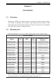
Chapter 1: Introduction Chapter 1 Introduction 1-1 Overview Supermicro’s SC846 4U chassis features a unique and highly optimized design. The chassis is equipped with redundant high-efficiency power supplies. Highperformance fans provide ample optimized cooling and twenty-four hot-swappable drive bays offer maximum storage capacity. 1-2 Shipping List Visit www.supermicro.com for the latest shipping lists for your chassis model.
SC846 Chassis Manual 1-3 Where to get Replacement Components Though not frequently, you may need replacement parts for your system. To ensure the highest level of professional service and technical support, we strongly recommend purchasing exclusively from our Supermicro Authorized Distributors/ System Integrators/Resellers. A list of Supermicro Authorized Distributors/System Integrators/Resellers can be found at: http://www.supermicro.com. Click the Where to Buy link.
Chapter 1: Introduction 1-4 Contacting Supermicro Headquarters Address: Super Micro Computer, Inc. 980 Rock Ave. San Jose, CA 95131 U.S.A. Tel: +1 (408) 503-8000 Fax: +1 (408) 503-8008 Email: marketing@supermicro.com (General Information) support@supermicro.com (Technical Support) Web Site: www.supermicro.com Europe Address: Super Micro Computer B.V. Het Sterrenbeeld 28, 5215 ML 's-Hertogenbosch, The Netherlands Tel: +31 (0) 73-6400390 Fax: +31 (0) 73-6416525 Email: sales@supermicro.
SC846 Chassis Manual 1-5 Returning Merchandise for Service A receipt or copy of your invoice marked with the date of purchase is required before any warranty service will be rendered. You can obtain service by calling your vendor for a Returned Merchandise Authorization (RMA) number. When returning to the manufacturer, the RMA number should be prominently displayed on the outside of the shipping carton, and mailed prepaid or hand-carried.
Chapter 2: Warning Statements for AC Systems Chapter 2 Standardized Warning Statements for AC Systems 2-1 About Standardized Warning Statements The following statements are industry standard warnings, provided to warn the user of situations which have the potential for bodily injury. Should you have questions or experience difficulty, contact Supermicro's Technical Support department for assistance. Only certified technicians should attempt to install or configure components.
xxx Chassis User's Manual Warnung WICHTIGE SICHERHEITSHINWEISE Dieses Warnsymbol bedeutet Gefahr. Sie befinden sich in einer Situation, die zu Verletzungen führen kann. Machen Sie sich vor der Arbeit mit Geräten mit den Gefahren elektrischer Schaltungen und den üblichen Verfahren zur Vorbeugung vor Unfällen vertraut. Suchen Sie mit der am Ende jeder Warnung angegebenen Anweisungsnummer nach der jeweiligen Übersetzung in den übersetzten Sicherheitshinweisen, die zusammen mit diesem Gerät ausgeliefert wurden.
Warning Statements for AC Systems 안전을 위한 주의사항 경고! 이 경고 기호는 위험이 있음을 알려 줍니다. 작업자의 신체에 부상을 야기 할 수 있는 상태에 있게 됩니다. 모든 장비에 대한 작업을 수행하기 전에 전기회로와 관련된 위험요소들을 확인하시고 사전에 사고를 방지할 수 있도록 표준 작업절차를 준수해 주시기 바랍니다. 해당 번역문을 찾기 위해 각 경고의 마지막 부분에 제공된 경고문 번호를 참조하십시오 BELANGRIJKE VEILIGHEIDSINSTRUCTIES Dit waarschuwings symbool betekent gevaar. U verkeert in een situatie die lichamelijk letsel kan veroorzaken.
xxx Chassis User's Manual Installation Instructions Warning! Read the installation instructions before connecting the system to the power source. 設置手順書 システムを電源に接続する前に、設置手順書をお読み下さい。 警告 将此系统连接电源前,请先阅读安装说明。 警告 將系統與電源連接前,請先閱讀安裝說明。 Warnung Vor dem Anschließen des Systems an die Stromquelle die Installationsanweisungen lesen. ¡Advertencia! Lea las instrucciones de instalación antes de conectar el sistema a la red de alimentación.
Chapter 2: Warning Statements for AC Systems Circuit Breaker Warning! This product relies on the building's installation for short-circuit (overcurrent) protection. Ensure that the protective device is rated not greater than: 250 V, 20 A.
xxx Chassis User's Manual 경고! 이 제품은 전원의 단락(과전류)방지에 대해서 전적으로 건물의 관련 설비에 의존합니다. 보호장치의 정격이 반드시 250V(볼트), 20A(암페어)를 초과하지 않도록 해야 합니다. Waarschuwing Dit product is afhankelijk van de kortsluitbeveiliging (overspanning) van uw electrische installatie. Controleer of het beveiligde aparaat niet groter gedimensioneerd is dan 220V, 20A.
Chapter 2: Warning Statements for AC Systems ¡Advertencia! El sistema debe ser disconnected de todas las fuentes de energía y del cable eléctrico quitado de los módulos de fuente de alimentación antes de tener acceso el interior del chasis para instalar o para quitar componentes de sistema. Attention Le système doit être débranché de toutes les sources de puissance ainsi que de son cordon d'alimentation secteur avant d'accéder à l'intérieur du chassis pour installer ou enlever des composants de systéme.
xxx Chassis User's Manual Equipment Installation Warning! Only trained and qualified personnel should be allowed to install, replace, or service this equipment. 機器の設置 トレーニングを受け認定された人だけがこの装置の設置、交換、 またはサービスを許可 されています。 警告 只有经过培训且具有资格的人员才能进行此设备的安装、更换和维修。 警告 只有經過受訓且具資格人員才可安裝、更換與維修此設備。 Warnung Das Installieren, Ersetzen oder Bedienen dieser Ausrüstung sollte nur geschultem, qualifiziertem Personal gestattet werden.
Chapter 2: Warning Statements for AC Systems Waarschuwing Deze apparatuur mag alleen worden geïnstalleerd, vervangen of hersteld door geschoold en gekwalificeerd personeel. Restricted Area Warning! This unit is intended for installation in restricted access areas. A restricted access area can be accessed only through the use of a special tool, lock and key, or other means of security. (This warning does not apply to workstations).
xxx Chassis User's Manual 경고! 이 장치는 접근이 제한된 구역에 설치하도록 되어있습니다. 특수도구, 잠금 장치 및 키, 또는 기타 보안 수단을 통해서만 접근 제한 구역에 들어갈 수 있습니다. Waarschuwing Dit apparaat is bedoeld voor installatie in gebieden met een beperkte toegang. Toegang tot dergelijke gebieden kunnen alleen verkregen worden door gebruik te maken van speciaal gereedschap, slot en sleutel of andere veiligheidsmaatregelen. Battery Handling Warning! There is the danger of explosion if the battery is replaced incorrectly.
Chapter 2: Warning Statements for AC Systems Warnung Bei Einsetzen einer falschen Batterie besteht Explosionsgefahr. Ersetzen Sie die Batterie nur durch den gleichen oder vom Hersteller empfohlenen Batterietyp. Entsorgen Sie die benutzten Batterien nach den Anweisungen des Herstellers. Attention Danger d'explosion si la pile n'est pas remplacée correctement. Ne la remplacer que par une pile de type semblable ou équivalent, recommandée par le fabricant.
xxx Chassis User's Manual Redundant Power Supplies Warning! This unit might have more than one power supply connection. All connections must be removed to de-energize the unit. 冗長電源装置 このユニットは複数の電源装置が接続されている場合があります。 ユニットの電源を切るためには、すべての接続を取り外さなければなりません。 警告 此部件连接的电源可能不止一个,必须将所有电源断开才能停止给该部件供电。 警告 此裝置連接的電源可能不只一個,必須切斷所有電源才能停止對該裝置的供電。 Warnung Dieses Gerät kann mehr als eine Stromzufuhr haben. Um sicherzustellen, dass der Einheit kein trom zugeführt wird, müssen alle Verbindungen entfernt werden.
Chapter 2: Warning Statements for AC Systems 경고! 이 장치에는 한 개 이상의 전원 공급 단자가 연결되어 있을 수 있습니다. 이 장치에 전원을 차단하기 위해서는 모든 연결 단자를 제거해야만 합니다. Waarschuwing Deze eenheid kan meer dan één stroomtoevoeraansluiting bevatten. Alle aansluitingen dienen verwijderd te worden om het apparaat stroomloos te maken. Backplane Voltage Warning! Hazardous voltage or energy is present on the backplane when the system is operating. Use caution when servicing.
xxx Chassis User's Manual 경고! 시스템이 동작 중일 때 후면판 (Backplane)에는 위험한 전압이나 에너지가 발생 합니다. 서비스 작업 시 주의하십시오. Waarschuwing Een gevaarlijke spanning of energie is aanwezig op de backplane wanneer het systeem in gebruik is. Voorzichtigheid is geboden tijdens het onderhoud. Comply with Local and National Electrical Codes Warning! Installation of the equipment must comply with local and national electrical codes.
Chapter 2: Warning Statements for AC Systems Attention L'équipement doit être installé conformément aux normes électriques nationales et locales. 경고! 현 지역 및 국가의 전기 규정에 따라 장비를 설치해야 합니다. Waarschuwing Bij installatie van de apparatuur moet worden voldaan aan de lokale en nationale elektriciteitsvoorschriften. Product Disposal Warning! Ultimate disposal of this product should be handled according to all national laws and regulations.
xxx Chassis User's Manual ¡Advertencia! Al deshacerse por completo de este producto debe seguir todas las leyes y reglamentos nacionales. Attention La mise au rebut ou le recyclage de ce produit sont généralement soumis à des lois et/ou directives de respect de l'environnement. Renseignez-vous auprès de l'organisme compétent. 경고! 이 제품은 해당 국가의 관련 법규 및 규정에 따라 폐기되어야 합니다.
Chapter 2: Warning Statements for AC Systems 警告 當您從機架移除風扇裝置,風扇可能仍在轉動。小心不要將手指、螺絲起子和其他 物品太靠近風扇。 Warnung Die Lüfter drehen sich u. U. noch, wenn die Lüfterbaugruppe aus dem Chassis genommen wird. Halten Sie Finger, Schraubendreher und andere Gegenstände von den Öffnungen des Lüftergehäuses entfernt. ¡Advertencia! Los ventiladores podran dar vuelta cuando usted quite ell montaje del ventilador del chasis.
xxx Chassis User's Manual Power Cable and AC Adapter Warning! When installing the product, use the provided or designated connection cables, power cables and AC adaptors. Using any other cables and adaptors could cause a malfunction or a fire. Electrical Appliance and Material Safety Law prohibits the use of UL or CSA -certified cables (that have UL/CSA shown on the code) for any other electrical devices than products designated by Supermicro only.
Chapter 2: Warning Statements for AC Systems Attention Lors de l'installation du produit, utilisez les bables de connection fournis ou désigné. L'utilisation d'autres cables et adaptateurs peut provoquer un dysfonctionnement ou un incendie. Appareils électroménagers et de loi sur la sécurité Matériel interdit l'utilisation de UL ou CSA câbles certifiés qui ont UL ou CSA indiqué sur le code pour tous les autres appareils électriques que les produits désignés par Supermicro seulement.
xxx Chassis User's Manual Notes 2-20
Chapter 3: System Interface Chapter 3 System Interface 3-1 Overview There are several LEDs on the control panel as well as others on the drive carriers to keep you constantly informed of the overall status of the system as well as the activity and health of specific components. Most SC846 models have two buttons on the chassis control panel: a reset button and a power on/off switch. This chapter explains the meanings of all LED indicators and the appropriate responses you may need to take.
SC846 Chassis Manual 3-2 Control Panel Buttons There are two push-buttons located on the left handle of the chassis. These are (in order from top to bottom) a power on/off button and a reset button. Power: The main power button is used to apply or remove power from the power supply to the server system. Turning off system power with this button removes the main power but keeps standby power supplied to the system. Therefore, you must unplug system before servicing.
Chapter 3: System Interface HDD: Indicates IDE channel activity. SAS/SATA drive, and/or DVD-ROM drive activity when flashing. 1 NIC1: Indicates network activity on GLAN1 when flashing. 2 NIC2: Indicates network activity on GLAN2 when flashing. Overheat/Fan Fail: When this LED flashes, it indicates a fan failure. When continuously on (not flashing) it indicates an overheat condition, which may be caused by cables obstructing the airflow in the system or the ambient room temperature being too warm.
SC846 Chassis Manual 3-4 Drive Carrier LEDs Your chassis uses SAS/SATA. SAS/SATA Drives Each SAS/SATA drive carrier has two LEDs. • Blue: Solid on = Drive is present and available. Blinking = Drive is actively being accessed. Each Serial ATA drive carrier has a blue LED. When illuminated in a solid on state, this blue LED (on the front of the SAS/SATA drive carrier) indicates drive activity.
Chapter 4: Chassis Setup and Maintenance Chapter 4 Chassis Setup and Maintenance 4-1 Overview This chapter covers the steps required to install components and perform maintenance on the chassis. The only tool you will need to install components and perform maintenance is a Phillips screwdriver. Print this chapter to use as a reference while setting up your chassis. For SC846B model chassis, see Appendix F of this manual, as the installation procedures differ for this chassis model.
SC846 Chassis Manual 4-2 Removing the Chassis Cover 4 2 2 3 Remove this screw (if necessary) Release Tab Figure 4-1: Removing the Chassis Cover Removing the Chassis Cover 1. Power down the system and remove the power cords from the back of the power supplies. 2. Press the release tabs to remove the cover from the locked position. Press both tabs at the same time. 3. Once the top cover is released from the locked position, slide the cover toward the rear of the chassis. 4.
Chapter 4: Chassis Setup and Maintenance 4-3 Installing Hard Drives 2 1 Figure 4-2: Removing a Hard Drive Carrier The SC846 features hot-swappable hard drives in carriers that can be removed from the chassis without powering down the server. Removing Hard Drive Carriers from the Chassis 1. Press the release button on the drive carrier. This extends the drive carrier handle. 2. Use the handle to pull the drive out of the chassis.
SC846 Chassis Manual Dummy Drive Drive Carrier Figure 4-3: Chassis Drive Carrier The drives are mounted in drive carriers to simplify their installation and removal from the chassis. These carriers also help promote proper airflow for the drive bays. Warning: Except for short periods of time (swapping hard drives), do not operate the server with the hard drive bays empty. 1 1 Figure 4-4: Removing a Dummy Drive from the Drive Carrier Installing a Hard Drive into the Hard Drive Carrier 1.
Chapter 4: Chassis Setup and Maintenance SAS/SATA Hard Drive 4 4 Drive Carrier Figure 4-5: Installing the Hard Drive into the Drive Carrier 2. Slide the hard drive into the carrier with the printed circuit board side facing down. 3. Carefully align the mounting holes in both the drive carrier and the hard drive. 4. Secure the hard drive to the carrier using six screws. 5. Replace the drive carrier into the chassis. Make sure to close the drive carrier handle to lock the drive carrier into place.
SC846 Chassis Manual 4-4 Installing the Motherboard I/O Shield Figure 4-7: I/O Shield Placement I/O Shield The I/O shield holds the motherboard ports in place. Install the I/O shield before you install the motherboard. Installing the I/O Shield 1. Review the documentation that came with your motherboard. Become familiar with component placement, requirements, and precautions. 2.
Chapter 4: Chassis Setup and Maintenance Pan head Flat head [0.197] [0.197] Round h M2.6 x 5 [0.19 Round head M3 x 5 mm [0.197] 6-32 x 5 mm 6-32 Standoffs x 5 mm Permanent and Optional Standoffs prevent short circuits byRAIL securing space between the motherboard and the chassis surface. The SC846 chassis includes permanent standoffs in locations used by most motherboards. These standoffs accept the rounded Phillips head screws included in the SC846 accessories packaging.
SC846 Chassis Manual Figure 4-9: Motherboard Installation 4. Place the motherboard in the chassis aligning the permanent and optional standoffs 5. Secure the motherboard to the chassis using the rounded, Phillips head screws. Do not exceed eight pounds of torque when tightening down the motherboard. 6. Secure the CPU(s), heatsinks, and other components to the motherboard as described in the motherboard documentation. 7.
Chapter 4: Chassis Setup and Maintenance Expansion Card Setup PCI Card Slots Figure 4-11: Installing Expansion Cards The SC846 chassis includes PCI slots for expansion cards. Installing Expansion Cards in the SC846 Chassis: 1. Power down the system, remove the power cords from the rear of the power supplies, lay the chassis on a flat surface, and open the chassis cover as described in Section 4-1. 2. Remove the screw holding the cover in place for each PCI slot you want to use.
SC846 Chassis Manual 4-5 Installing the Air Shroud Figure 4-12: Air Shroud for SC846LP Chassis Air shrouds concentrate airflow to maximize fan efficiency. The SC846 chassis air shroud does not require screws to set up Installing the Air Shroud 1. Power down the system, remove the power cords from the rear of the power supplies and remove the cover as described in Section 4-1. 2. Confirm that your air shroud matches your chassis model. Each shroud is labeled SC846LP, SC846RC, or SC846U. 3.
Chapter 4: Chassis Setup and Maintenance 4-6 Checking the Server's Airflow Checking the Airflow 1. Make sure there are no objects to obstruct airflow in and out of the server. 2. Do not operate the server without drives or drive carriers in the drive bays. Use only recommended server parts. 3. Make sure no wires or foreign objects obstruct air flow through the chassis. Pull all excess cabling out of the airflow path or use shorter cables. The control panel LEDs inform you of system status.
SC846 Chassis Manual 4-7 System Fans Five heavy-duty system fans (three front fans and two rear fans) provide cooling for the chassis. These fans circulate air through the chassis as a means of lowering the chassis internal temperature. Release Tab Release Tab Figure 4-13: Front System Fan Figure 4-14: Rear System Fan Replacing a System Fan 1. If necessary, open the chassis while the power is running to determine which fan has failed.
Chapter 4: Chassis Setup and Maintenance Figure 4-15: Placing the Front System Fan Figure 4-16: Placing the Rear System Fan 4-13
SC846 Chassis Manual 4-8 Power Supply The SC846 chassis has either a 710, 900, 920 or 1200 Watt, high-efficiency redundant power supply. This power supply is auto-switching capable. This enables it to automatically sense and operate at a 100v to 240v input voltage. An amber light will be illuminated on the power supply when the power is off. An illuminated green light indicates that the power supply is operating.
Chapter 4: Chassis Setup and Maintenance Release Tab Figure 4-17: Power Supply Release Tab Changing the Power Supply: 1. Your chassis includes a redundant power supply with two power modules which enables you to leave the system running and remove one power supply. If your server has only one power supply installed, you must power down the system and unplug the power cord. 2.
SC846 Chassis Manual 3 Figure 4-18: Removing the Power Supply 3. Pull the power supply out using the handle provided. 4. Replace the failed power module with another of the same model. 5. Push the new power supply module into the power bay until it clicks into the locked position. 6. Plug the power cord back into the rear of the power module and power up the system.
Chapter 4: Chassis Setup and Maintenance 4-9 Changing the Power Distributor Server chassis above 2U require a power distributor. The power distributor provides failover and power supply redundancy. In the unlikely event that you must change the power distributor, do following: Changing the Power Distributor Power down the system, disconnect the power cords from the back of the power supplies, lay the chassis on a flat surface, and open the chassis cover. 1.
SC846 Chassis Manual 3. Remove the two screws securing the power distributor housing to the chassis wall 4. Remove the three screws securing the power distributor to the housing. 5. Gently pull the power distributor and housing from the chassis. Carefully guide all the cables through the power distributor housing. 6. Remove the power distributor from the housing. 7. Slide the new power distributor module into the power distributor housing.
Chapter 4: Chassis Setup and Maintenance 4-10 Changing the CD-ROM or DVD-ROM and HDD Trays The SC846 chassis supports the following drive configuration options: Position Description Position A N/A (Default), or single 3.5" HDD tray, or dual 2.5" HDD tray. Position B Dummy cover (default), or single 3.5" HDD tray, single 2.5" HDD tray, DVD, or FDD.
SC846 Chassis Manual 2. Install the fixed hard drive into the hard drive tray using four round head screws (6-32) and two Mylar washers. Mylar Washer Screw 6-32 Fixed Screw 6-32 Screw 6-32 Figure 4-22: Securing the Fixed Hard Drive into the Tray 3. Lower the drive and tray into the chassis, carefully inserting the lower rubberlined holes onto the pins at the base of the chassis and aligning the upper rubber holes with the holes in the chassis. 4.
Chapter 4: Chassis Setup and Maintenance 5. Connect the power and data cables from the drive to other chassis components including the motherboard and power distributor board.
SC846 Chassis Manual 4-11 Accessing the Backplane The SC846 chassis backplane is located behind the hard drives and in front of the front system fans. In order to change jumper settings on the backplane, it may be necessary to remove the backplane from the chassis. Removing the Backplane 1. Power down the system, remove the power cords from the back of the power supplies and remove the chassis cover. 2. Disconnect the cabling to the backplane. 3.
Chapter 4: Chassis Setup and Maintenance 4. Remove the five lower screws securing the backplane housing to the chassis floor and set these aside for later use. Remove Five Lower Screws 4 Figure 4-26: Removing the Lower Backplane Housing Screws 5. Gently ease the backplane up and out of the chassis.
SC846 Chassis Manual Installing the Backplane 1. Gently slide the backplane and its housing back into position in the chassis. 1 Slide the Backplane into the Chassis Figure 4-28: Replacing the Backplane in the Chassis 2. Replace the five lower screws which secure the backplane housing to the chassis floor.
Chapter 4: Chassis Setup and Maintenance 3. Replace the four upper screws which secure the backplane housing to the chassis. 4. Reconnect the cabling to the backplane.
SC846 Chassis Manual Notes 4-26
Chapter 5: Rack Installation Chapter 5 Rack Installation 5-1 Overview This chapter provides a quick setup checklist to install the chassis into a rack. Following these steps in the order given should enable you to have the system installed within a minimal amount of time. 5-2 Unpacking the System You should inspect the box which the chassis was shipped in and note if it was damaged in any way. If the chassis itself shows damage, you should file a damage claim with the carrier who delivered it.
SC846 Chassis Manual 5-4 • Warnings and Precautions Rack Precautions Ensure that the leveling jacks on the bottom of the rack are fully extended to the floor with the full weight of the rack resting on them. • In single rack installations, stabilizers should be attached to the rack. • In multiple rack installations, the racks should be coupled together. • • • • • • • • Always make sure that the rack is stable before extending a component from the rack.
Chapter 5: Rack Installation Rack Mounting Considerations Ambient Operating Temperature If installed in a closed or multi-unit rack assembly, the ambient operating temperature of the rack environment may be greater than the ambient temperature of the room. Therefore, consideration should be given to installing the equipment in an environment compatible with the manufacturer’s maximum rated ambient temperature (TMRA).
SC846 Chassis Manual 5-6 Rack Mounting Instructions This section provides information on installing the chassis into a rack unit with the rails provided. There are a variety of rack units on the market, which may mean that the assembly procedure will differ slightly from the instructions provided. You should also refer to the installation instructions that came with the rack unit you are using. NOTE: This rail will fit a rack between 26.5" and 36.4" deep.
Chapter 5: Rack Installation Locking Tabs Each inner rail has a locking tab. This tab locks the chassis into place when installed and pushed fully into the rack. These tabs also lock the chassis in place when fully extended from the rack. This prevents the server from coming completely out of the rack when when the chassis is pulled out for servicing. Releasing the Inner Rail Releasing Inner Rail from the Outer Rails 1. Identify the left and right outer rail assemblies as described on page 5-4. 2.
SC846 Chassis Manual Inner Rails 14 2 14 3 Figure 5-3: Installing the Inner Rails Figure 5-4: Inner Rails Installed on the Chassis (The chassis above are an example only. Actual chassis may differ slightly) Installing The Inner Rails on the Chassis Installing the Inner Rails 1. Confirm that the left and right inner rails have been correctly identified. 2. Place the inner rail firmly against the side of the chassis, aligning the hooks on the side of the chassis with the holes in the inner rail. 3.
Chapter 5: Rack Installation 1 L-min=676.00(26.61")(outer rail) 12 14 21D01 13 Figure 5-5: Extending and Releasing the Outer Rails Installing the Outer Rails on the Rack Installing the Outer Rails 1. Press upward on the locking tab at the rear end of the middle rail. 2. Push the middle rail back into the outer rail. 3. Hang the hooks of the front of the outer rail onto the slots on the front of the rack. If necessary, use screws to secure the outer rails to the rack, as illustrated above. 4.
SC846 Chassis Manual Ball-Bearing Shuttle Figure 5-6: Installing into a Rack Standard Chassis Installation Installing the Chassis into a Rack 1. Confirm that the inner rails are properly installed on the chassis. 2. Confirm that the outer rails are correctly installed on the rack. 3. Pull the middle rail out from the front of the outer rail and make sure that the ball-bearing shuttle is at the front locking position of the middle rail. 4. Align the chassis inner rails with the front of the middle rails.
Chapter 5: Rack Installation Optional Quick Installation Method The following quick installation method may be used to install the chassis onto a rack. Installing the Chassis into a Rack 1. Install the whole rail assembly onto the rack as described on page 5-7. 2. Release the inner rail without retracting the middle rail. 3. Install the inner rails on the chassis as previously described on page 5-6. 4. Install the chassis onto the middle rail as described in the previous section.
SC846 Chassis Manual Notes 5-10
Appendix A: Chassis Cables Appendix A SC846 Cables and Hardware A-1 Overview This appendix lists supported cables for your chassis system. It only includes the most commonly used components and configurations. For more compatible cables, refer to the manufacturer of the motherboard you are using and our Web site at: www.supermicro.com.
SC846 Chassis Manual A-3 Compatible Cables These cables are compatible with the SC846 Chassis. Alternate SAS/SATA Cables Some compatible motherboards have different connectors. If your motherboard has only one SAS connector that the SAS/SATA cables must share, use one of the following cables. These cables must be purchased separately. Cable Name: SAS Cable Quantity: 1 Part #: CBL-0175L Alt.
Appendix A: Chassis Cables Extending Power Cables Although Supermicro chassis are designed with to be efficient and cost-effective, some compatible motherboards have power connectors located in different areas. To use these motherboards you may have to extend the power cables to the mother boards. To do this, use the following chart as a guide. Power Cable Extenders Number of Pins Cable Part # Length 24-pin CBL-0042 7.9” (20 cm) 20-pin CBL-0059 7.9” (20 cm) 8-pin CBL-0062 7.
SC846 Chassis Manual A-4 Chassis Screws The accessory box includes all the screws needed to set up your chassis. This section lists and describes the most common screws used. Your chassis may not require all the parts listed. M/B HARD DRIVE Flat head 6-32 x 5 mm [0.197] Pan head 6-32 x 5 mm [0.197] DVD-ROM, CD-ROM, and FLOPPY DRIVE Pan head 6-32 x 5 mm [0.197] Flat head 6-32 x 5 mm [0.197] Round head M3 x 5 mm [0.197] Round head M2.6 x 5 mm [0.197] RAIL Flat head M4 x 4 mm [0.
Appendix B: Power Supply Specifications Appendix B SC846 Power Supply Specifications This appendix lists power supply specifications for your chassis system. SC846TQ-R900B, SC846E1-R900B and SC846E2-R900B 900W MFR Part # PWS-902-1R Rated AC Voltage 100 - 240V 50 - 60Hz 3 - 4 Amp +5V standby 4 Amp +12V 75 Amp +5V 50 Amp +3.3V 30 Amp -12V 0.
SC846 Chassis Manual SC846E16-R200B, SC846E26-R1200B, SC846TQ-R1200B, SC846A-R1200B 1200W MFR Part # PWS-1K21P-1R AC Input 100 - 140V, 50 - 60Hz, 8 - 11.5 Amp 180 - 240V, 50 - 60Hz, 5.5 - 8 Amp 1000W, 83 Amp @ 100-140V DC Output 1200W, 100 Amp @ 180-240V +12V 5Vsb: 4A +5V: 50 Amp DC Output with +3.3V: 30 Amp PDB -12V: 0.
Appendix C: SAS-846TQ Backplane Specifications Appendix C SAS-846TQ Backplane Specifications To avoid personal injury and property damage, carefully follow all the safety steps listed below when accessing your system or handling the components. C-1 ESD Safety Guidelines Electriostatic Discharge (ESD) can damage electronic components. To prevent damage to your system, it is important to handle it very carefully. The following measures are generally sufficient to protect your equipment from ESD.
SC846 Chassis Manual C-3 A Note to Users All images and layouts shown in this user's guide are based upon the latest PCB Revision available at the time of publishing. The card you have received may or may not look exactly the same as the graphics shown in this manual. C-4 Introduction to the SAS-846TQ Backplane The SAS-846TQ backplane has been designed to utilize the most up-to-date technology available, providing your system with reliable, high-quality performance.
Appendix C: SAS-846TQ Backplane Specifications C-4 Front Connectors and Jumpers 1 2 1 1 1 12 12 13 13 111 14 15 18 10 1 10 1 10 1 17 10 1 13 16 19 10 1 Figure C-1: Front Connectors Front Connectors 1. Chip: MG 9072 2. Upgrade Connectors: JP69, JP78 and JP115 3. ACT_IN: JP26, JP47, and JP108 4. I2C Connector #1 (JP37) and #2 (JP95) 5. I2C Connector #3 (JP52) and #4 (JP96) 6. I2C Connector #5 (JP116) and #6 (JP117) C-3 7. Sideband Connector #1 (JP66) and #2 (JP68) 8.
SC846 Chassis Manual 34 1 33 1 32 1 31 1 30 1 29 1 28 1 27 1 26 1 25 1 24 1 23 1 22 1 21 1 20 1 19 1 18 1 17 1 16 1 15 1 14 1 13 1 12 1 111 Figure C-2: SAS Ports 11. 12. 13. 14. 15. 16. 17. 18. 19. SAS SAS SAS SAS SAS SAS SAS SAS SAS Port Port Port Port Port Port Port Port Port #0 #1 #2 #3 #4 #5 #6 #7 #8 J5 J14 J26 J40 J6 J16 J29 J41 J7 20. 21. 22. 23. 24. 25. 26. 27. 28. 29. 30. 31. 32. 33. 34.
Appendix C: SAS-846TQ Backplane Specifications C-5 Front Connector and Pin Definitions 1. MG9072 Chip The MG9072 is an enclosure management chip that supports the SES-2 controller and SES-2 protocols. 2. Upgrade Connectors The upgrade connectors are designated JP69, JP78, and JP115 and are used for manufacturer's diagnostic purposes only. 3. Activity LED Header The activity LED header, designated JP26, JP47 and JP108, is used to indicate the activity status of each SAS drive.
SC846 Chassis Manual 7. - 9. Sideband Headers Sideband Headers The sideband headers are designated JP66, JP68, JP75, JP77, JP112, and JP114. For SES-2 to work properly, you must connect an 8-pin sideband cable. See the table to the right for pin definitions. NOTE: SGPIO is the default setting for this backplane.
Appendix C: SAS-846TQ Backplane Specifications C-6 Front Jumper Locations and Pin Definitions JP35 JP50 JP97 JP98 JP99 JP100 JP129 JP61 JP84 JP62 JP63 JP64 Figure C-3: Front Jumpers Explanation of Jumpers To modify the operation of the backplane, jumpers can be used to choose between optional settings. Jumpers create shorts between two pins to change the function of the connector. Pin 1 is identified with a square solder pad on the printed circuit board.
SC846 Chassis Manual Jumper Settings Jumper Jumper Settings Note JP35 1-2: Reset 2-3: Default MG 9072 chip reset #1 JP50 1-2: Reset 2-3: Default MG 9072 chip reset #2 JP129 1-2: Reset 2-3: Default MG 9072 chip reset #3 Fan Jumper Settings This backplane can use up to four fans. To utilize each fan, you must configure both jumpers as instructed below.
Appendix C: SAS-846TQ Backplane Specifications I2C and SGPIO Modes and Jumper Settings This backplane can utilize I2C or SGPIO. SGPIO is the default mode and can be used without making changes to your jumper. The following information details which jumper must be configured to use SGPIO mode or restore your backplane to I2C mode.
SC846 Chassis Manual Front LED Indicators D53 D54 D45 D47 D49 D51 D3 D36 D89 Figure C-4: Front LEDs Front Panel LEDs LED State Specification D45 On Failure in Fan #1 D47 On Failure in Fan #2 D49 On Failure in Fan #3 D51 On Failure in Fan #4 D3 On Alarm #1: Overheat/drive failure in Channel 1 D36 On Alarm #2: Overheat/drive failure in Channel 2 D89 On Alarm #3: Overheat/drive failure in Channel 3 D53 Off +5V: Backplane power failure. Light is on during normal operation.
Appendix C: SAS-846TQ Backplane Specifications C-7 Rear Connectors and LED Indicators SAS #20 SAS #21 SAS #22 SAS #23 SAS #16 SAS #17 SAS #18 SAS #19 SAS #12 SAS #13 SAS #14 SAS #15 SAS #8 SAS #9 SAS #10 SAS #11 SAS #4 SAS #5 SAS #6 SAS #7 SAS #0 SAS #1 SAS #2 SAS #3 ACT #0 FAIL #0 Figure C-5: Rear Connectors and LEDs Rear SAS/SATA Connectors Rear Connector SAS Drive Number Rear Connector SAS Drive Number SAS #0 SAS/SATA HDD #0 SAS #12 SAS/SATA HDD #12 SAS #1 SAS/SATA HDD
SC846 Chassis Manual Rear LED Indicators Hard Drive Activity Failure LED SAS #0 Rear LED D12 D5 SAS #1 D22 D23 SAS #2 D40 D37 SAS #3 D102 D107 SAS #4 D13 D6 SAS #5 D24 D29 SAS #6 D41 D38 SAS #7 D104 D108 SAS #8 D14 D7 SAS #9 D25 D30 SAS #10 D42 D39 SAS #11 D106 D109 SAS #12 D15 D8 SAS #13 D26 D31 SAS #14 D87 D88 SAS #15 D111 D110 SAS #16 D18 D19 SAS #17 D27 D32 SAS #18 D100 D103 SAS #19 D118 D119 SAS #20 D21 D20 SAS #21 D28 D33 SAS #22 D
Appendix D: SAS-846EL Backplane Specifications Appendix D SAS-846EL Backplane Specifications To avoid personal injury and property damage, carefully follow all the safety steps listed below when accessing your system or handling the components. D-1 ESD Safety Guidelines Electrotatic Discharge (ESD) can damage electronic components. To prevent damage to your system, it is important to handle it very carefully. The following measures are generally sufficient to protect your equipment from ESD.
SC846 Chassis Manual D-3 An Important Note to Users All images and layouts shown in this user's guide are based upon the latest PCB Revision available at the time of publishing. The card you have received may or may not look exactly the same as the graphics shown in this manual. D-4 Introduction to the SAS-846EL Backplane The SAS-846EL backplane has been designed to utilize the most up-to-date technology available, providing your system with reliable, high-quality performance.
Appendix D: SAS-846EL Backplane Specifications D-5 Front Connectors and Jumpers 1 1 2 1 1 2 BUZZER_ENB1 REMOTE_FAN_FAIL_SOCKET1 OVERHEATFAIL1 A C A C FANFAIL1 SEC_I2C1 SEC_J2 SEC_IPMI1 SEC_J1 SEC_J0 PRI_J2 PRI_J1 PRI_J0 PRI_IPMI1 SEC_MODE1 BUZZER1 PRI_I2C1 L1 13 1 12 1 WWN 111 10 1 SAS846EL2 19 18 REV 1.
SC846 Chassis Manual D-6 Front Connector and Pin Definitions 1. and 2. Optional Primary and Secondary I2C Connectors The optional I2C connectors are connected to the CSE-PTJBOD-CB2 board and are used to monitor the power supply status and to control the fans. See the table on the right for pin definitions. I2C Connector Pin Definitions Pin# Definition 1 Data 2 Ground 3 Clock 4 No Connection 3.
Appendix D: SAS-846EL Backplane Specifications 7. Fan Connectors Fan Connectors The 3-pin connectors, designated FAN1, FAN2, and FAN3, provide power to the fans. See the table on the right for pin definitions. 8 - 13. SAS Ports The primary and secondary sets of SAS ports provide expander features including cascading and failover From right to left the ports are primary 1/2/3 and secondary 1/2/3.
SC846 Chassis Manual D-7 Front Jumper Locations and Pin Definitions BUZZER_ENB1 REMOTE_FAN_FAIL_SOCKET1 OVERHEATFAIL1 FANFAIL1 SEC_MODE1 BUZZER_ENB1 REMOTE_FAN_FAIL_SOCKET1 OVERHEATFAIL1 A C A C FANFAIL1 SEC_I2C1 SEC_J2 SEC_IPMI1 SEC_J1 SEC_J0 PRI_J2 PRI_J1 PRI_J0 PRI_IPMI1 SEC_MODE1 BUZZER1 PRI_I2C1 L1 WWN SAS846EL2 REV 1.
Appendix D: SAS-846EL Backplane Specifications General Jumper Settings Jumper Jumper Settings Note PRI_MODE1 1-2 Factory Setting Do not change SEC_MODE1 1-2 Factory Setting Do not change BUZZER_ENB1 Open: Disable Closed: Enable Buzzer Enable* *The buzzer sound indicates that a condition requiring immediate attention has occurred. The buzzer alarm is triggered by the following conditions: 1. Hard drive failure 2. Fan failure 3. System temperature over 45º Celsius.
SC846 Chassis Manual D-8 Rear Connectors and LED Indicators CA R247 A FAIL#21 FAIL21 R249 ACT#20 ACT20 C R246 CA A C555 FAIL#20 FAIL20 R248 C552 C542 FAIL14 R236 C539 C547 ACT19 AC CA R243 ACT#13 C C482 ACT13 R231 ACT#19 C483 J20 C A SEC_SRAM2 FAIL#14 D70 C559 SAS #20 FAIL#13 D69 C488 R224 C480 C538 C534 FAIL#19 FAIL19 R245 C530 C529 C524 C518 A FAIL13 R233 A C481 SAS #19 J19 ACT#18 ACT18 ACT12 R242 F6 C A ACT#12 R230 C C C ACT21 ACT#21 A C A C CA C
Appendix D: SAS-846EL Backplane Specifications Rear LED Indicators Hard Drive Activity LED Failure LED SAS #0 Rear Connector ACT #0 FAIL #0 SAS #1 ACT #1 FAIL #1 SAS #2 ACT #2 FAIL #2 SAS #3 ACT #3 FAIL #3 SAS #4 ACT #4 FAIL #4 SAS #5 ACT #5 FAIL #5 SAS #6 ACT #6 FAIL #6 SAS #7 ACT #7 FAIL #7 SAS #8 ACT #8 FAIL #8 SAS #9 ACT #9 FAIL #9 SAS #10 ACT #10 FAIL #10 SAS #11 ACT #11 FAIL #11 SAS #12 ACT #12 FAIL #12 SAS #13 ACT #13 FAIL #13 SAS #14 ACT #14 FAIL #14
Appendix D: SAS-846EL Backplane Specifications D-9 Dual Port and Cascading Configurations The following section contains cascading configurations for the SC846EL1 and SC846EL2 backplanes. D-10 Single and Dual Port Expanders Single Ports SAS-846EL1 backplanes have a single-port expander that access all twenty-four drives and supports cascading. Dual Ports SAS-846EL2 backplanes have dual-port expanders that access all twenty-four drives.
SC846 Chassis Manual D-11 Failover The SAS-846EL2 backplane has two expanders which allow effective failover. Single Host Bus Adapter SAS HBA In a single host bus configuration, the backplane connects to one Host Bus Adapter (HBA).
Appendix D: SAS-846EL Backplane Specifications D-12 Failover with RAID Cards and Multiple HBAs The SAS-836EL backplane may be configured for failover with multiple HBAs using either RAID controllers or HBAs to acheive failover protection. RAID Controllers: If RAID controllers are used, then the failover is accomplished through port failover on the same RAID card.
SC846 Chassis Manual D-13 Chassis Power Card and Support Cables Chassis Power Card In a cascaded configuration, the first chassis includes a motherboard and at least one Host Bus Adapter (HBA). Other servers in this enclosed system, include a power card. This section describes the supported power card for the SAS-846 series backplane. For more information, see the PCC-JBPWR2 power card manual. This manual can be found at the http://www.supermicro.com or as an appendix in the SAS-846EL chassis manual.
Appendix D: SAS-846EL Backplane Specifications Connecting an Internal Host Bus Adapter to the Backplane The following section lists the most common cables used to connect the Host Bus Adapter (HBA) to the backplane.
SC846 Chassis Manual Cable Name: iPass (Mini-SAS) to iPass (Mini-SAS) Part #: CBL-0108L-02 Length: 39 cm (15 inches) Part #: CBL-0109L-02 Length: 22 cm (9 inches) Part #: CBL-0110L-02 Length: 18 cm (7 inches) Description: This cable has an iPass (SFF-8087/Mini-SAS) connector (36-pin) at each end. It connects from the HBA to the SAS-846EL backplane.
Appendix D: SAS-846EL Backplane Specifications Connecting an External Host Bus Adapter to the Backplane This backplane supports external Host Bus Adapters. In this configuration, the HBA and the backplane are in different physical chassis. This allows a JBOD configuration system to connect to the other system that has a HBA.
SC846 Chassis Manual Supported External HBA to Backplane Cable Use the following cable if your external HBA has an InfiniBand connector. Figure D-15: SAS InfiniBand Cable (CBL-0200L) Cable Name: SAS InfiniBand to Mini-SAS X4 1M cable, PBF Part #: CBL-0200L Length: 1 meter Description: This cable has an InfiniBand connector (SFF-8470) on one end and an SFF-8088-1X (26-pin) at the other end.
Appendix D: SAS-846EL Backplane Specifications Connecting Multiple Backplanes in a Single Channel Environment This section describes the cables used when cascading from a single HBA. These connections use CBL-0167L internal cables and CBL-0166L external cables.
SC846 Chassis Manual Single HBA Configuration Cables Single Port Cable Assembly Figure D-17: Single Port Internal Cable (CBL-0167L) Cable Name: SAS EL2/EL1 Backplane Cable (Internal) with 2-port Cascading Cable, 68 cm Part #: CBL-0167L (SFF-8087 to SFF-8088 x1) Ports: Single Placement: Internal cable Description: Internal cable. Connects the backplane to the Host Bus Adapter (HBA) or external port. Used in single port environments.
Appendix D: SAS-846EL Backplane Specifications Connecting Multiple Backplanes in a Dual Channel Environment This section describes the cables used when cascading from dual HBAs. These connections use CBL-0168L internal cables and CBL-0166L external cables.
SC846 Chassis Manual Dual HBA Configuration Cables Dual Port Cable Assembly Figure D-20: Dual Port Internal Cable (CBL-0168L) Cable Name: SAS Dual-port Cable Assembly, 68/76 cm Part #: CBL-0168L Ports: Dual Placement: Internal cable Description: Internal cascading cable. Connects the backplane to the Host Bus Adapter (HBA) or external port. Used in dual port environments.
Appendix D: SAS-846EL Backplane Specifications 3-5 Supported Cascading Configurations Cascading allows the system to access data at a faster rate by allowing several backplanes to share resources to reduce latency time. The first backplane in a cascaded system requires a motherboard and HBA. Other servers require a power control card with no motherboard and no HBA. For more information, see the SC846 Chassis Manual available at www.supermicro.com.
SC846 Chassis Manual Server System with Single SAS HBA The expanders allow horizontal branching. This configuration also applies to dual ports.
Appendix D: SAS-846EL Backplane Specifications Dual SAS HBA and Cascaded Configuration PRI_J2 SEC_J2 SEC_J0 PRI_J1 SEC_J1 PRI_J0 WWN Port B Expander 2 Port A Expander 1 J17 HBA Dual Port Cable Assembly HBA Cable 0168L (internal cable) PRI_J2 SEC_J2 SEC_J0 Cable 0166L (External cables) PRI_J1 SEC_J1 PRI_J0 WWN Port B Expander 2 Port A Expander 1 J17 Power Card PRI_J2 SEC_J2 SEC_J0 PRI_J1 SEC_J1 PRI_J0 WWN Port B Expander 2 Port A Expander 1 J17 Power Card Figure D-24: Dual SAS HB
SC846 Chassis Manual Dual SAS HBA and Cascaded Configuration with Branching Port B Ex. 2 Port A Ex. 1 Port B Ex. 2 Port A Ex. 1 Power Card HBA HBA Port B Ex. 2 Port A Ex. 1 Port B Ex. 2 Port A Ex. 1 Power Card Power Card Cable 0166L (External cable) Port B Ex. 2 Port A Ex. 1 Port B Ex. 2 Port A Ex.
Appendix E: SAS2-846EL Backplane Specifications Appendix E SAS2-846EL Backplane Specifications To avoid personal injury and property damage, carefully follow all the safety steps listed below when accessing your system or handling the components. E-1 ESD Safety Guidelines Electrostatic Discharge (ESD) can damage electronic components. To prevent damage to your system, it is important to handle it very carefully. The following measures are generally sufficient to protect your equipment from ESD.
SC846 Chassis User's Manual E-3 An Important Note to Users All images and layouts shown in this user's guide are based upon the latest PCB Revision available at the time of publishing. The card you have received may or may not look exactly the same as the graphics shown in this manual. E-4 Introduction to the SAS2-846EL Backplane The SAS2-846EL backplane has been designed to utilize the most up-to-date technology available, providing your system with reliable, high-quality performance.
Appendix E: SAS2-846EL Backplane Specifications E-5 Front Connectors and Jumpers BPN-SAS2-846EL2 DESIGNED IN USA 12 1 FAN_MONITOR_DISABLE BUZZER_ENB1 REV 1.
SC846 Chassis User's Manual E-6 Front Connector and Pin Definitions 1. Primary I2C Connector The I2C connector is used to monitor the power supply status and to control the fans. See the table on the right for pin definitions. I2C Connector Pin Definitions Pin# Definition 1 Data 2 Ground 3 Clock 4 No Connection 2. Backplane Main Power Connectors The 4-pin connectors, designated PWR1, PWR2, PWR3, PWR4, PWR5, and PWR6, provide power to the backplane.
Appendix E: SAS2-846EL Backplane Specifications 6. Fan Connectors Fan Connectors The 3-pin connectors, designated FAN1, through FAN3, provide power to the fans. See the table on the right for pin definitions. 7. - 13. SAS Connectors The primary and secondary sets of SAS connectors provide expander features including cascading and failover. From right to left the ports are Primary 0, Primary 1 and Secondary 0, Secondary 1. Note that secondary SAS ports are not present on the SAS2-846EL1 backplane.
SC846 Chassis User's Manual E-7 Front Jumper Locations and Settings FANFAIL_LED_DISABLE BUZZER_ENB1 BPN-SAS2-846EL2 FAN_MONITOR_DISABLE BUZZER_ENB1 DESIGNED IN USA ACTLED1 ACTLED1 MH6 SEC_J1 SEC_J2 + BUZZER1 MH8 SEC_J0 PRI_J2 A C OVERHEATFAIL1 A C MH14 FANFAIL_LED_DISABLE PRI_J0 EC20 EC6 EC5 + + EC12 + EC11 + 1 FANFAIL1 EC24 EC22 EC26 1 + MDIO1 MDIO2 + + + FAN_MONITOR_DISABLE L147 PRI_J1 + MH12 R4631 R4635 MH9 1 1 1 1 REV 1.
Appendix E: SAS2-846EL Backplane Specifications General Jumper Settings Jumper Jumper Settings Note PRI_MODE1 and 2 2-3 Factory Setting Do not change SEC_MODE1 and 2 2-3 Factory Setting Do not change EXPDBG1 and 2 No jumper required Debug, SMC internal use only.
SC846 Chassis User's Manual Rear Connectors and LED Indicators A C A C A C C C A C C A C C C A C ACT21 ACT#21 C A C C A C CA A C C C A C A C C CA A C A A A C A ACT12 FAIL#18 C ACT18 ACT#18 4 SAS #19 A A SAS #18 A FAIL12 FAIL#12 FAIL6 J12 SAS #12 A A C ACT#12 CA FAIL19 J19 FAIL#19 FAIL13 SAS #19 C CA CA C A C A C A A C A C ACT19 ACT#19 FAIL#13 A SAS #20 ACT13 C FAIL#20 FAIL20 33 C A J20 49 32 ACT#13 C A ACT20 ACT#20 6
Appendix E: SAS2-846EL Backplane Specifications Rear LED Indicators Hard Drive Activity LED Failure LED SAS #0 Rear Connector ACT #0 FAIL #0 SAS #1 ACT #1 FAIL #1 SAS #2 ACT #2 FAIL #2 SAS #3 ACT #3 FAIL #3 SAS #4 ACT #4 FAIL #4 SAS #5 ACT #5 FAIL #5 SAS #6 ACT #6 FAIL #6 SAS #7 ACT #7 FAIL #7 SAS #8 ACT #8 FAIL #8 SAS #9 ACT #9 FAIL #9 SAS #10 ACT #10 FAIL #10 SAS #11 ACT #11 FAIL #11 SAS #12 ACT #12 FAIL #12 SAS #13 ACT #13 FAIL #13 SAS #14 ACT #14 FAIL #14
SC846 Chassis User's Manual E-10 Single and Dual Port Expanders Single Ports SAS2-846EL1 backplanes have a single-port expander that accesses all hard drives and supports cascading. Dual Ports SAS2-846EL2 backplanes have dual-port expanders that access all the hard drives. These dual-port expanders support cascading, failover, and multipath.
Appendix E: SAS2-846EL Backplane Specifications E-11 Failover The SAS2-846EL2 backplane has two expanders which allow effective failover. SAS HBA Single Host Bus Adapter In a single host bus configuration, the backplane connects to one Host Bus Adapter (HBA). BPN-SAS2-846EL2 DESIGNED IN USA MH9 1 1 1 R4631 R4635 FAN_MONITOR_DISABLE BUZZER_ENB1 REV 1.
SC846 Chassis User's Manual E-12 Chassis Power Card and Support Cables Chassis Power Card In a cascaded configuration, the first chassis includes a motherboard and at least one host bus adapter. Other servers in this enclosed system, include a power card. This section describes the supported power card for the SAS2-846EL series backplanes.
Appendix E: SAS2-846EL Backplane Specifications Connecting an Internal Host Bus Adapter to the Backplane The following section lists the most common cables used to connect the host bus adapter to the backplane. HBA BPN-SAS2-846EL2 DESIGNED IN USA MH9 1 1 1 R4631 R4635 FAN_MONITOR_DISABLE BUZZER_ENB1 REV 1.
SC846 Chassis User's Manual Cable Name: iPass (Mini-SAS) to iPass (Mini-SAS) Part #: CBL-0108L-02 Length: 39 cm (15 inches) Part #: CBL-0109L-02 Length: 22 cm (9 inches) Part #: CBL-0110L-02 Length: 18 cm (7 inches) Description: This cable has an iPass (SFF-8087/Mini-SAS) connector (36-pin) at each end. It connects from the HBA to the SAS2-846EL backplane. Supported External HBA to Backplane Cable Use the following cable if your external HBA has an InfiniBand connector.
Appendix E: SAS2-846EL Backplane Specifications Connecting an External Host Bus Adapter to the Backplane This backplane supports external Host Bus Adapters. In this configuration, the HBA and the backplane are in different physical chassis. This allows a JBOD configuration system to connect to the other system that has a HBA. Single External Host Bus Adapter BPN-SAS2-846EL2 DESIGNED IN USA MH9 1 1 1 R4631 R4635 FAN_MONITOR_DISABLE BUZZER_ENB1 REV 1.
SC846 Chassis User's Manual Supported External HBA to Backplane Cable Use the following cable if your external HBA has an InfiniBand connector. Figure E-10: External Cable (CBL-0166L) Cable Name: SAS EL2/EL1 Cascading Cable (External), 68 cm Part #: CBL-0166L (SFF-8088 1x to SFF-8088 x1) Ports: Single or Dual Placement: External cable Description: External cascading cable. Connects ports between servers.
Appendix E: SAS2-846EL Backplane Specifications Connecting Multiple Backplanes in a Single Channel Environment This section describes the cables used when cascading from a single HBA. These connections use CBL-0167L internal cables and CBL-0166L external cables. BPN-SAS2-846EL2 DESIGNED IN USA MH9 1 1 1 R4631 R4635 FAN_MONITOR_DISABLE BUZZER_ENB1 REV 1.
SC846 Chassis User's Manual Single HBA Configuration Cables Single Port Cable Assembly Figure E-12: Single Port Internal Cable (CBL-0167L) Cable Name: SAS EL2/EL1 Backplane Cable (Internal) with 2-port Cascading Cable, 68 cm Part #: CBL-0167L (SFF-8087 to SFF-8088 x1) Ports: Single Placement: Internal cable Description: Internal cable. Connects the backplane to the Host Bus Adapter (HBA) or external port. Used in single port environments.
Appendix E: SAS2-846EL Backplane Specifications Connecting Multiple Backplanes in a Dual Channel Environment This section describes the cables used when cascading from dual HBAs. These connections use CBL-0168L internal cables and CBL-0166L external cables. BPN-SAS2-846EL2 DESIGNED IN USA MH9 1 1 1 R4631 R4635 FAN_MONITOR_DISABLE BUZZER_ENB1 REV 1.
SC846 Chassis User's Manual Dual HBA Configuration Cables Dual Port Cable Assembly Figure E-15: Dual Port Internal Cable (CBL-0168L) Cable Name: SAS Dual-port Cable Assembly, 68/76 cm Part #: CBL-0168L Ports: Dual Placement: Internal cable Description: Internal cascading cable. Connects the backplane to the HBA or external port. Used in dual port environments.
Appendix E: SAS2-846EL Backplane Specifications E-13 Supported Cascading Configurations Cascading allows the system to access data at a faster rate by allowing several backplanes to share resources to reduce latency time. The first backplane in a cascaded system requires a motherboard and an HBA. Other servers require a power control card with no motherboard and no HBA. For more information, see the SC846 Chassis Manual available at www.supermicro. com.
SC846 Chassis User's Manual Dual SAS HBA and Cascaded Configuration HBA BPN-SAS2-846EL2 DESIGNED IN USA MH9 1 1 1 R4631 R4635 FAN_MONITOR_DISABLE BUZZER_ENB1 REV 1.
Appendix F: SC846B Chassis Specifications Appendix F SC846B Chassis Specifications F-1 Overview This appendix provides assembly instructions specific to SC846B model chassis only. F-2 Revisions to the Data in this Appendix Content Revision History Date 12/16/11 F-3 Revision 1.0 Changes Initial revision Installation Instructions for SC846B Models The SC846B model chassis is specially designed with two peripheral drive bays located in the rear of the chassis.
SC846 Chassis Manual F-4 Installing a DVD-ROM Drive Identifying the DVD-ROM Drive Components Use the photograph below to identify the components which are required to install the DVD-ROM drive into the rear peripheral bay of the SC846B chassis: 1F 1E 1D 1B 1C 1A Figure F-1: SC846B DVD-ROM Components DVD-ROM Drive Components A. Lower bracket B. DVD-ROM drive C. DVD-ROM backplane D. Upper bracket E. SATA cable F.
Appendix F: SC846B Chassis Specifications Installing a DVD-ROM Drive 1. Disconnect the power from the chassis by unplugging the power cord. 2. Remove the screws securing the dummy cover into the rear peripheral drive bay. This bay is located on the rear of the chassis beside the power supplies. 3. Lift the dummy cover up and out of the peripheral drive bay. 13 12 Figure F-2: Removing the Dummy Cover from the Peripheral Drive Bay 4.
SC846 Chassis Manual 6. Place the drive onto the lower bracket and align the mounting holes in the drive with those in the bracket. 7. Use four mounting screws to secure the lower bracket to the drive. 17 16 17 Figure F-4: Installing the Lower Bracket onto the DVD-ROM Drive 8. Place the upper bracket onto the drive and align the mounting holes in the drive with the holes in the upper bracket. 9. Secure the upper bracket to the drive using two screws as shown below.
Appendix F: SC846B Chassis Specifications 10. Place the DVD-ROM assembly into the chassis, positioning it so that the bottom bracket is against the interior wall of the power supply bay and the front of the DVD-ROM drive is accessible through the opening of the rear DVDROM bay. 11. Align the mounting holes in the DVD-ROM with those in the interior wall of the power supply bay and those on the exterior at the rear of the chassis between the DVD-ROM bay and the power supply bay.
SC846 Chassis Manual F-5 Installing the Hard Drive Assembly Identifying the Hard Drive Assembly Components Use the photograph below to identify the components which are required to install the hard drvie into the rear peripheral bay of the SC846B chassis: 1D 1C 1E 1A 1B Figure F-6: SC846B Hard Drive Assembly Components Hard Drive Assembly Components A. Two 2.5" hard drive carriers B. Hard drive cage C. Two SATA cables D. Hard drive backplane E.
Appendix F: SC846B Chassis Specifications Installing the Hard Drive Assembly 1. Disconnect the power from the chassis by unplugging the power cord. 2. Remove the screws securing the dummy cover into the rear peripheral drive bay. This bay is located on the rear of the chassis beside the power supplies. 3. Lift the dummy cover up and out of the peripheral drive bay. 13 12 Figure F-7: Removing the Dummy Cover from the Peripheral Drive Bay 4.
SC846 Chassis Manual 6. Remove the dummy drives from the hard drive carriers. 7. Insert a drive into the carrier with the PCB side facing down and the connector end toward the rear of the carrier. 8. Align the drive in the carrier so that the mounting holes of both are aligned. Note that there are holes in the carrier marked "SAS" or “SATA” to aid in correct installation. 9. Secure the drive to the carrier with four screws as illustrated above.
Appendix F: SC846B Chassis Specifications 12. Place the hard drive assembly into the chassis, positioning it so that the mounting holes in the front of the hard drive align with those in the front of the the chassis and the mounting holes in the interior wall of the power supply bay align with those on the hard drive cage. 13.
SC846 Chassis Manual Disclaimer (cont.) The products sold by Supermicro are not intended for and will not be used in life support systems, medical equipment, nuclear facilities or systems, aircraft, aircraft devices, aircraft/emergency communication devices or other critical systems whose failure to perform be reasonably expected to result in significant injury or loss of life or catastrophic property damage.