
User`s manual


C-4
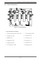
SC842 Chassis Manual
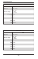
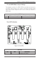
#4 and #5. Sideband Connectors
The sideband connectors are designated JP51
and JP52. For SES-2 to work properly, you
must connect an 8-pin sideband cable. See the
table to the right for pin denitions.
Sideband Connectors
Pin # Denition Pin # Denition
2 SDIN/
Backplane
Addressing
(SB5)
1 Controller
ID (SB6)
4 SDOUT/I
2
C
Reset
(SB4)
3 GND (SB2)
6 GND (SB3) 5 SLOAD/
SDA (SB1)
8 Backplane
ID (SB7)
7 SCLOCK/
SCL (SB0)
#3. MG9072 Chip
The MG9072 is an enclosure management
chip that supports the SES-2 controller and
SES-2 protocols.
C-6 Front Connector and Pin Denitions
#2 Upgrade Connector
The upgrade connector is designated JP46
and is for the manufacturer's diagnostic pur-
poses only.
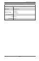
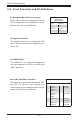
Backplane
Main Power
4-Pin Connector
Pin# Denition
1 +12V
2 and 3 Ground
4 +5V
#1. Backplane Main Power Connectors
These 4-pin connectors designated JP10 and
JP13 provide power to the backplane. See the
table on the right for pin denitions.