SUPER ® SC842 Chassis Series SC842TQ-865B SC842TQ-665B SC842i-500B SC842XTQ-R606B USER’S MANUAL 1.
SC842 Chassis Manual The information in this User’s Manual has been carefully reviewed and is believed to be accurate. The vendor assumes no responsibility for any inaccuracies that may be contained in this document, makes no commitment to update or to keep current the information in this manual, or to notify any person or organization of the updates. Please Note: For the most up-to-date version of this manual, please see our web site at www.supermicro.com. Super Micro Computer, Inc.
Preface Preface About This Manual This manual is written for professional system integrators and PC technicians. It provides information for the installation and use of the SC842 chassis. Installation and maintenance should be performed by experienced technicians only. Optimized for enterprise level server systems, Supermicro's SC842 chassis series supports serverboards that demand high-volume I/O or computational usage.
SC842 Chassis Manual Manual Organization Chapter 1: Introduction The first chapter provides a checklist of the main components included with this chassis and describes the primary features of the SC842 chassis. This chapter also includes contact information. Chapter 2: System Safety This chapter lists warnings, precautions, and system safety.
Preface Table of Contents Chapter 1 Introduction 1-1 Overview.......................................................................................................... 1-1 1-2 Shipping List..................................................................................................... 1-1 Part Numbers................................................................................................... 1-1 1-3 Chassis Features...........................................................................
SC842 Chassis Manual Removing Hard Drive Carriers (SC842TQ and SC842XTQ).......................... 5-3 Installing a Drive to the Carrier (SC842TQ and SC842XTQ).......................... 5-4 Installing Hard Drive Carriers (SC842TQ and SC842XTQ)............................ 5-5 Removing the Hard Drive Cage (SC842i Series)............................................ 5-6 Installing Hard Drives into the Cage (SC842i Series)..................................... 5-7 Installing the Hard Drive Cage (SC842i Series)..
Preface Appendix A SC842 Chassis Cables Appendix B SC842 Power Supply Specifications Appendix C SAS-842TQ Backplane Specifications vii
SC842 Chassis Manual Notes viii
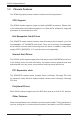
Chapter 1 Introduction Chapter 1 Introduction 1-1 Overview Supermicro’s SC842 4U chassis features a unique and highly-optimized design. The chassis is equipped with a high-efficiency power supply. High-performance fans provide ample optimized cooling. Up to five 3.5" drives provide maximum storage capacity in a 4U form factor. 1-2 Shipping List Part Numbers Please visit the Supermicro Web site for the latest shipping lists and part numbers for your particular chassis model: http://www.supermicro.
SC842 Chassis Manual 1-3 Chassis Features The SC842 high-performance chassis includes the following features: CPU Support The SC842 chassis supports single and dual Intel/AMD processors. Please refer to the motherboard specifications pages on our Web site for updates on supported processors, at www.supermicro.com. Hot-Swappable Hard Drives The SC842TQ model chassis features hard drive bays which support up to five hot-swappable 3.5" SAS/SATA hard drives.
Chapter 1 Introduction Contacting Supermicro Headquarters Address: Super Micro Computer, Inc. 980 Rock Ave. San Jose, CA 95131 U.S.A. Tel: +1 (408) 503-8000 Fax: +1 (408) 503-8008 Email: marketing@supermicro.com (General Information) support@supermicro.com (Technical Support) Web Site: www.supermicro.com Europe Address: Super Micro Computer B.V. Het Sterrenbeeld 28, 5215 ML 's-Hertogenbosch, The Netherlands Tel: +31 (0) 73-6400390 Fax: +31 (0) 73-6416525 Email: sales@supermicro.
SC842 Chassis Manual Notes 1-4
Chapter 2 System Safety Chapter 2 System Safety 2-1 Overview This chapter provides safety information about the SC842 chassis. These instructions assume that you are an experienced technician, familiar with common concepts and terminology. 2-2 Warnings and Precautions You should inspect the box the chassis was shipped in and note if it was damaged in any way. If the chassis itself shows damage, file a damage claim with the carrier who delivered your system.
SC842 Chassis Manual 2-4 Electrical Safety Precautions Basic electrical safety precautions should be followed to protect yourself from harm and the SC842 from damage: • • • • • • • • Be aware of the locations of the power on/off switch on the chassis as well as the room’s emergency power-off switch, disconnection switch or electrical outlet. If an electrical accident occurs, you can then quickly remove power from the system. Do not work alone when working with high-voltage components.
Chapter 2 System Safety • Please handle used batteries carefully. Do not damage the battery in any way; a damaged battery may release hazardous materials into the environment. Do not discard a used battery in the garbage or a public landfill. Please comply with the regulations set up by your local hazardous waste management agency to dispose of your used battery properly. • 2-5 • • • • • 2-6 DVD-ROM laser: CAUTION - This server may have come equipped with an optional DVD-ROM drive.
SC842 Chassis Manual • Use a grounded wrist strap designed to prevent electrostatic discharge. • Keep all components and printed circuit boards (PCBs) in their antistatic bags • • • • • • until ready for use. Touch a grounded metal object before removing any board from its antistatic bag. Do not let components or PCBs come into contact with your clothing, which may retain a charge even if you are wearing a wrist strap.
Chapter 3 Chassis Components Chapter 3 Chassis Components 3-1 Overview This chapter describes the most common components included with your chassis. Some components listed may not be included or compatible with your particular chassis model. For more information, see the installation instructions detailed later in this manual. 3-2 Components Hard Drives and Peripheral Drives The SC842 chassis supports up to five hot-swappable 3.
SC842 Chassis Manual rated at 600 Watts. (Model SC842XTQ) In the unlikely event of a power supply failure, replacement is easily accomplished without tools. 3-3 Where to get Replacement Components Although not frequently, you may need replacement parts for your system. To ensure the highest level of professional service and technical support, we strongly recommend purchasing exclusively from our Supermicro Authorized Distributors/ System Integrators/Resellers.
Chapter 4 System Interface Chapter 4 System Interface 4-1 Overview There are several LEDs on the control panel as well as others on the drive carriers to keep you constantly informed of the overall status of the system as well as the activity and health of specific components. SC842 models have two buttons on the chassis control panel: a reset button and an on/off switch. This chapter explains the meanings of all LED indicators and the appropriate response you may need to take.
SC842 Chassis Manual 4-2 Control Panel Buttons There are two push-buttons located on the front of the chassis. These are (in order from left to right), a reset button and a power on/off button. Reset: The reset button is used to reboot the system. Power: The main power switch is used to activate or remove power from the power supply to the server system. Turning off system power with this button removes the main power but keeps standby power supplied to the system.
Chapter 4 System Interface Overheat/Fan Fail: When this LED flashes it indicates a fan failure. When continuously on (not flashing) it indicates an overheat condition, which may be caused by cables obstructing the airflow in the system or the ambient room temperature being too warm. Check the routing of the cables and make sure all fans are present and operating normally. You should also check to make sure that the chassis covers are installed. Finally, verify that the heatsinks are installed properly.
SC842 Chassis Manual 4-4 Drive Carrier LEDs Each hard drive carrier has two LEDs. Blue: When illuminated, this blue LED (on the front of the drive carrier) indicates drive activity. A connection to the backplane enables this LED to blink on and off when that particular drive is being accessed. Red: The red LED to indicate a drive failure. If one of the hard drives fails, replace it with a compatible enterprise-level hard drive model.
Chapter 5 Chassis Setup and Maintenance Chapter 5 Chassis Setup and Maintenance 5-1 Overview This chapter details the basic steps required to install components to the SC842 chassis. The only tool you will need is a Phillips head screwdriver. Print this chapter to use as a reference while setting up your chassis. ! Review the warnings and precautions listed in the manual before setting up or servicing this chassis.
SC842 Chassis Manual 5-2 Removing the Chassis Cover 12 1 3 2 Figure 5-1: Removing the Chassis Cover Removing the Chassis Cover 1. Remove the screw at the rear of the chassis and set it aside for later use. 2. Remove the two screws on the sides of the cover and set them aside. 3. Lift the cover up and off the chassis. ! Warning: Except for short periods of time, do NOT operate the chassis without the cover in place. The chassis cover must be in place to allow proper airflow and prevent overheating.
Chapter 5 Chassis Setup and Maintenance 5-3 Installing Hot-Swap Hard Drives The hot-swappable hard drives are mounted in drive carriers to simplify their installation and removal from the chassis. The SC842 chassis supports up to five 3.5" hard drives. Removing Hard Drive Carriers (SC842TQ and SC842XTQ) Removing the Hard Drive and Hard Drive Carriers 1. Press the release button on the drive carrier. This extends the drive carrier handle. 2. Use the handle to pull the drive carrier out of the chassis.
SC842 Chassis Manual Installing a Drive to the Carrier (SC842TQ and SC842XTQ) Installing a Hard Drive 1. Remove the two screws securing the dummy drive to the drive carrier. 2. Lift the dummy drive out of the drive carrier. 3. Place the hard drive carrier on a flat, stable surface such as a desk, table, or work bench. 4. Slide the hard drive into the carrier with the printed circuit board side facing down. 5. Carefully align the mounting holes in the hard drive and the carrier.
Chapter 5 Chassis Setup and Maintenance SAS/SATA Hard Drive Hard Drive Carrier 6 4 6 Use a hard, stable surface when installing the hard drive Figure 5-4: Installing a Drive into a Hard Drive Carrier Installing Hard Drive Carriers (SC842TQ and SC842XTQ) Installing the Hard Drive Carriers 1. Reinsert the hard drive carrier into the hard drive bay. 2. Gently push in the handle, which locks the drive carrier into the drive bay.
SC842 Chassis Manual Removing the Hard Drive Cage (SC842i Series) Removing the Hard Drive Cage 1. Power down the system and disconnect the chassis from any source of power. 2. Remove the four screws securing the internal hard drive cage and bracket to the chassis as illustrated below and set them aside for later use. 3. Gently push the internal hard drive cage out through the front of the chassis.
Chapter 5 Chassis Setup and Maintenance 1 Insert Drive 12 Secure with two to three screws in the top of the drive 13 Secure with two to three screws in the corresponding holes in the bottom of the drive Figure 5-6: Installing Hard Drives into the Internal Hard Drive Cage Installing Hard Drives into the Cage (SC842i Series) Installing Drives into the Internal Hard Drive Cage 1. Insert a hard drive into the hard drive cage, aligning the holes in the drive with those in the cage. 2.
SC842 Chassis Manual Installing the Hard Drive Cage (SC842i Series) Installing the Hard Drive Cage 1. Shut down the system using the operating system, remove the power cord from the rear of the chassis and open the chassis cover. 2. Insert the hard drive cage through the front of the chassis. 3. Reinstall the four screws which were previously set aside to secure the hard drive cage and bracket to the chassis as illustrated below.
Chapter 5 Chassis Setup and Maintenance 5-4 Installing an I/O Shield Installing an I/O Shield I/O shields help to hold the motherboard ports in place. Install the I/O shield that came with your motherboard before installing the motherboard. 1. Shut down the system using the operating system, remove the power cord from the rear of the chassis and open the chassis cover. 2. Locate the I/O shield. 3. Push the I/O shield gently into the rear opening of the chassis, until it clicks into the secure position.
SC842 Chassis Manual 5-5 Installing the Motherboard Optional Standoffs Standoffs prevent short circuits by creating space between the motherboard and the chassis floor. The SC842 chassis includes optional removeable standoffs in locations used by motherboards. These standoffs accept the round Phillips head screws included in the SC842 accessories packaging. To use an optional standoff, you must insert a hex head screw into the desired position on the chassis floor and secure it with a nut.
Chapter 5 Chassis Setup and Maintenance Figure 5-10: Installing the Motherboard Motherboard Installation Installing the Motherboard 1. Review the documentation that came with your motherboard. Become familiar with component placement, requirements, and precautions. 2. Shut down the system using the operating system, remove the power cord from the rear of the chassis and open the chassis cover. 3. Remove any packaging from the chassis. 4.
SC842 Chassis Manual Expansion Card Setup The SC842 chassis features PCI slots which support expansion cards. The SC842XTQ model (above) has eleven PCI slots. All other models (below) have seven PCI slots. PCI Slots for Expansion Cards Figure 5-11: PCI Slots Installing Expansion Cards 1. Shut down the system using the operating system, remove the power cord from the rear of the chassis and open the chassis cover. 2. Locate the motherboard port which is aligned with the card slot you want to install. 3.
Chapter 5 Chassis Setup and Maintenance Rear System Fans 12 Fan Release Tab 14 Figure 5-12: Installing the Rear Fan Installing the Rear System Fans The SC842 chassis includes two rear exhaust fans. Installing the Rear System Fans 1. Shut down the system using the operating system, remove the power cord from the rear of the chassis and open the chassis cover. 2. Press the fan release tab as illustrated above. 3. Pull the rear fan out of the back of the chassis. 4.
SC842 Chassis Manual Checking the Server's Airflow Checking the Airflow 1. Make sure there are no objects to obstruct the airflow in and out of the server. If necessary, route and organize the cables appropriately. 2. Do not operate the chassis without drive carriers in the drive bays.
Chapter 5 Chassis Setup and Maintenance 5-6 Power Supply Most SC842 chassis models include a single fixed 500, 665 or 865 Watt power supply. The SC842XTQ chassis model includes dual redundant 600 Watt power supplies. In the unlikely event of a power supply failure, single power supply systems must be powered-down, the power completely disconnected from the unit and the power supply removed using a Phillips head screw driver.
SC842 Chassis Manual 12 1 Release Button Replacing a Redundant Power Supply (SC842XTQ) Redundant power supplies are hot-swappable and it is not necessary to power down the server before replacing the power supply. Replacing the Redundant Power Supply 1. Press the release button on the rear of the failed power supply module 2. Grasp the handle on the power supply module and pull it out of the chassis. 3. Insert the replacement power supply module into the power supply bay. 4.
Chapter 5 Chassis Setup and Maintenance Installing the DVD-ROM and Peripheral Drive SC842 chassis models supports a slim DVD-ROM and up to three 5-1/4" peripheral drives. 13 Release Tab 14 Guide Screws Figure 5-14: Installing a Peripheral Drive Installing a Peripheral Drive 1. Shut down the system using the operating system, remove the power cord from the rear of the chassis and open the chassis cover. 2.
SC842 Chassis Manual Notes 5-18
Chapter 6 Rack Installation Chapter 6 Rack Installation 6-1 Overview This chapter provides a quick setup to install the chassis into a rack. Following these steps in the order given should enable you to complete the rack installation within a minimal amount of time. 6-2 Unpacking the System Inspect the box the chassis was shipped in and note if it was damaged in any way. If the chassis itself shows damage you should file a damage claim with the carrier who delivered it.
SC842 Chassis Manual • This product is for installation only in a Restricted Access Location (dedicated equipment rooms, service closets and similar environments). ! Warnings and Precautions! ! Rack Precautions • Ensure that the leveling jacks on the bottom of the rack are fully extended to the floor with the full weight of the rack resting on them. • In single rack installation, stabilizers should be attached to the rack. • In multiple rack installations, the racks should be coupled together.
Chapter 6 Rack Installation • Always keep the rack's front door and all panels and components on the servers closed when not servicing to maintain proper cooling. Rack Mounting Considerations Ambient Operating Temperature If installed in a closed or multi-unit rack assembly, the ambient operating temperature of the rack environment may be greater than the ambient temperature of the room.
SC842 Chassis Manual 6-4 Rack Mounting Rack Mounting Overview This section provides information on installing the SC842 chassis into an open rack. There are a variety of rack units on the market, which may mean the assembly procedure will differ slightly. You should also refer to the installation instructions that came with the rack unit you are using.
Chapter 6 Rack Installation 6-5 Rack Mounting with the Optional Rail System Rail System Overview This section provides information on installing the SC842 chassis into a four-post rack unit with the optional quick-release rails. There are a variety of rack units on the market, which may mean the assembly procedure will differ slightly. You should also refer to the installation instructions that came with the rack unit you are using.
SC842 Chassis Manual 13 12 13 1 Figure 6-3: Installing the Inner Rails Installing the Inner Rails Installing the Inner Rails 1. Place the inner rails on the side of the chassis aligning the hooks of the chassis with the rail holes. Make sure the rail faces "outward". 2. Slide the inner rail toward the front of the chassis. 3. Secure the chassis with two screws as illustrated. Repeat steps 1 and 2 for the other inner rail.
Chapter 6 Rack Installation 13 1 SCREW screw the handles t outer rails for secur purpose if necessar 12 Figure 6-4: Assembling the Outer Rails Outer Rack Rails Outer rails attach to the rack and hold the chassis in place. Installing the Outer Rails to the Rack 1. Secure the back end of the outer rail to the rack, using the screws provided. 2. Press the button where the two outer rails are joined to retract the smaller outer rail. 3.
2 F. SC842 Chassis Manual SCREW 1 Figure 6-5: Installing the Chassis into a Rack Installing the Chassis into a Rack 1. Extend the outer rails as illustrated above. 2. Align the inner rails of the chassis with the outer rails on the rack. 3. Slide the inner rails into the outer rails, keeping the pressure even on both sides. When the chassis has been pushed completely into the rack, it should click into the locked position. SCREW 4.
Appendix A Appendix A SC842 Chassis Cables A-1 Overview This appendix lists supported cables for your chassis system. It only includes the most commonly used components and configurations. For more compatible cables, refer to the manufacturer of the motherboard you are using and our Web site at: www.supermicro.com.
SC842 Chassis Manual SC842XTQ-R606B Part # Type Length Description CBL-0044L Cable 2' CBL-0087 Ribbon, Round 20" 16-pin to 16-pin ribbon cable for control panel CBL-0084L Cable 6" Front control cable, 16-pin split cable CBL-0286L Cable 30 cm 4-pin to 4-pin rear fan power extension with square header.
Appendix B Power Supply Appendix B SC842 Power Supply Specifications This appendix lists power supply specifications for your chassis system. SC842i-500B 500W MFR Part # PWS-502-PQ Rated AC Voltage 100 - 240V 50-60Hz 7-3.5 Amp +5V standby 3 Amp +12V1 17 Amp +12V2 17 Amp +12V3 17 Amp +12V4 18 Amp -12V 0.5 Amp +5V 20 Amp +3.
SC842 Chassis Manual SC842TQ-665B 665W MFR Part # PWS-665-PQ Rated AC Voltage 100 - 240V 50 - 60Hz 10 -5 Amps +5V standby 6 Amp +12V 54 Amp +5V 30 Amp +3.3V 24 Amp -12V 0.5 Amp SC842TQ-865B 865W MFR Part # PWS-865-PQ Rated AC Voltage 100 - 240V 50 - 60Hz 12 - 6 Amp +5V standby 6.5 Amp +12V 70 Amp +5V 30 Amp +3.
Appendix B Power Supply SC842XTQ-R606B 600W MFR Part # PWS-606P-1R Rated AC Voltage 100-240 V 50-60 Hz 7.5-3.
Appendix C SAS-842TQ Backplane Specifications Appendix C SAS-842TQ Backplane Specifications To avoid personal injury and property damage, carefully follow all the safety steps listed below when accessing your system or handling the components. C-1 ESD Safety Guidelines Electrostatic Discharge (ESD) can damage electronic components. To prevent damage to your system, it is important to handle it very carefully. The following measures are generally sufficient to protect your equipment from ESD.
SC842 Chassis Manual C-3 An Important Note to Users All images and layouts shown in this user's guide are based upon the latest backplane revision available at the time of publishing. The card you have received may or may not look exactly the same as the graphics shown in this manual. C-4 Introduction to the SAS-842TQ Backplane The SAS-842TQ backplane has been designed to utilize the most up-to-date technology available, providing your system with reliable, high-quality performance.
Appendix C SAS-842TQ Backplane Specifications C-5 Front Connectors 3 MH5 U40 MH4 JP29:9072 RST 1-2: RST 2-3: NO RST 1 JP29 JP53 JP54 3 D3:OH/DRIVE FAIL 33 48 JP33:MODE 1-2:SGPIO 2-3:I2C 49 D3 32 U25 DESIGNED IN USA 7 7 #1 #2 J8 J7 J6 7 7 7 J10 #3 JP13 1 #4 J5 UPGRADE JP25 16 18 #0 GND GND 4 JP44 SAS842TQ 2 +5V 16 1 7 1 U26 64 8 F1 1 JP25:OH TEMP.
SC842 Chassis Manual C-6 Front Connector and Pin Definitions #1. Backplane Main Power Connectors Backplane Main Power 4-Pin Connector These 4-pin connectors designated JP10 and JP13 provide power to the backplane. See the table on the right for pin definitions. Pin# Definition 1 +12V 2 and 3 Ground 4 +5V #2 Upgrade Connector The upgrade connector is designated JP46 and is for the manufacturer's diagnostic purposes only. #3.
Appendix C SAS-842TQ Backplane Specifications #6 and #7. I2C Connectors The I C connectors, designated JP44 and JP45, are used to monitor HDD activity and status. See the table on the right for pin definitions. I2C Connector Pin Definitions 2 #8 - #12. SAS/SATA Connectors The SAS/SATA connectors are numbered 0 through 4. Each may be connected to the system with a SAS or SATA cable.
SC842 Chassis Manual C-7 Front Jumper Locations and Pin Definitions JP29 JP53 48 JP29:9072 RST 1-2: RST 2-3: NO RST 1 JP29 SAS842TQ #1 #3 #2 J8 J7 J6 7 7 7 J10 #4 7 +5V GND GND +12V 1 JP13 DESIGNED IN USA 16 1 U26 1 F1 JP44 7 64 7 2 F2 3 JP25 F3 C35 C34 1 JP25 UPGRADE 8 4 JP25:OH TEMP.
Appendix C SAS-842TQ Backplane Specifications I2C and SGPIO Mode Jumper Settings This backplane can utilize I2C or SGPIO. SGPIO is the default mode and can be used without making changes to your jumpers. The following information details which jumpers must be configured to use I2C mode or restore your backplane to SGPIO mode.
SC842 Chassis Manual C-8 Rear Connectors and LED Indicators SAS #4 8 SAS #3 8 8 8 8 SAS #2 1 1 1 1 1 SAS #1 SAS#4 SAS#3 SAS#2 SAS#1 SAS#0 SAS #0 22 22 22 22 1 J9 J4 J3 J2 J1 22 FAIL#0 D5 C A D12 ACT#1 FAIL#1 ACT#0 C A D6 C C A A D13 C FAIL#3 ACT#2 FAIL#2 D7 A C A D14 D8 C FAIL#4 ACT#3 A C ACT#4 A D15 D19 C AC A D18 Figure C-4: Rear Connectors SECNARELOT ELGNA LAMICED 1. X 03 30. XX HSINIF HCAM 010X.
Appendix C SAS-842TQ Backplane Specifications SAS#4 SAS#3 SAS#2 SAS#1 SAS#0 1 1 1 1 1 8 8 8 8 8 22 22 22 22 1 J9 J4 J3 J2 J1 22 FAIL#0 D5 C A D12 ACT #0 FAIL #0 ACT#1 FAIL#1 ACT#0 C A D6 C C A A ACT #1 FAIL #1 D7 C FAIL#3 ACT#2 FAIL#2 D13 A C A D14 D8 C ACT #2 FAIL #2 FAIL#4 ACT#3 A C ACT#4 A D15 D19 AC C A D18 ACT #4 FAIL #4 ACT #3 FAIL #3 Figure C-5: Rear LEDs SECNARELOT ELGNA LAMICED 1. X 03 30. XX HSINIF HCAM 010X. XX 10.
SC842 Chassis Manual Disclaimer (cont.) The products sold by Supermicro are not intended for and will not be used in life support systems, medical equipment, nuclear facilities or systems, aircraft, aircraft devices, aircraft/emergency communication devices or other critical systems whose failure to perform be reasonably expected to result in significant injury or loss of life or catastrophic property damage.